Afterheat utilization device of sintering machine

A sintering machine, waste heat technology, applied in waste heat treatment, lighting and heating equipment, furnace components, etc., can solve the problem of flue gas temperature and flow fluctuations, the difficulty of continuous normal production of waste heat boilers, and the low operation rate of steam turbine generator sets. To the stability requirements and other issues, to achieve the effect of slowing down the load fluctuation, avoiding frequent start of the generator set, and stabilizing the operation of the generator set

Inactive Publication Date: 2013-03-20
JIANGSU YONGGANG GROUP CO LTD
View PDF3 Cites 3 Cited by
  • Summary
  • Abstract
  • Description
  • Claims
  • Application Information

AI Technical Summary

Problems solved by technology

[0003] Existing 300m 2 Half of the sintering machine will be equipped with a set of waste heat utilization device. The principle is to use the hot air in the first and second stages of the annular cooler process to generate steam to generate electricity through the waste heat boiler, and the flue gas temperature in the first stage (high temperature section) of the annular cooler process is about 350- 400 (450max) ℃, the flue gas temperature of the second stage (medium temperature section) of the annular cooler process is about 250-300°C, because the flue gas temperature and flow rate of the annular cooler fluctuate greatly, making it difficult for the waste heat boiler to continue normal production, resulting in The operating rate of the steam turbine generator set cannot meet the stable requirements (not less than 92%), and there is an urgent need for a device that can meet the normal and stable production of the waste heat boiler

Method used


Image

  • Afterheat utilization device of sintering machine

Examples


Embodiment

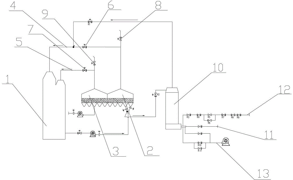
[0020] The structure of this embodiment is as figure 1 As shown, a sintering machine waste heat utilization device includes a waste heat boiler 1 and two sets of annular coolers 2 and 3 connected to the waste heat boiler, which are respectively connected to the waste heat boiler 1 through a high-temperature flue gas pipeline 4 and a medium-temperature flue gas pipeline 5. A high-temperature flue gas regulating valve 6 is installed on the section from the annular cooler 2 to the waste heat boiler of the flue gas pipeline 4, and a medium-temperature flue gas regulating valve 7 is installed on the section from the annular cooler 3 to the waste heat boiler of the medium-temperature flue gas pipeline 5. The end of the flue gas pipeline is provided with a high-temperature flue gas pipeline relief valve 8 and a medium-temperature flue gas pipeline relief valve 9 respectively, and a compensation hot blast stove 10 is also installed between the waste heat boiler 1 and the annular cooler...


PUM


Abstract

The invention relates to an afterheat utilization device, in particular to an afterheat utilization device of a sintering machine, and belongs to the technical field of machinery. The afterheat utilization device structurally comprises an afterheat boiler and an annular cooler communicated with the afterheat boiler. The sintering machine afterheat utilization device has an improvement point that a compensation hot air furnace is also arranged between the afterheat boiler and the annular cooler, the compensation hot air furnace is provided with an air inlet end and two air outlet ends, the air inlet end is respectively communicated with a liquefied gas pipe, a coal gas pipe and a combustion support air pipe, one air outlet end is communicated with the afterheat boiler through a corresponding air outlet pipeline, and the other air outlet end is communicated with a high-temperature smoke gas pipeline through the corresponding air outlet pipeline. The sintering machine afterheat utilization device has the beneficial effects that the economic benefits are obviously improved, the operation of a unit is stabilized, and the service life of the unit is prolonged.

Description

technical field [0001] The invention relates to a waste heat utilization device, in particular to a sintering machine waste heat utilization device, which belongs to [0002] in the field of mechanical technology. Background technique [0003] Existing 300m 2 Half of the sintering machine will be equipped with a set of waste heat utilization device. The principle is to use the hot air in the first and second stages of the annular cooler process to generate steam power through the waste heat boiler, and the flue gas temperature in the first stage (high temperature section) of the annular cooler process is about 350- 400 (450max) ℃, the flue gas temperature of the second stage (medium temperature section) of the annular cooler process is about 250-300°C, because the flue gas temperature and flow rate of the annular cooler fluctuate greatly, making it difficult for the waste heat boiler to continue normal production, resulting in The operating rate of the steam turbine ge...

Claims


Application Information

Patent Timeline
Patent Type & Authority Applications(China)
IPC IPC(8): F27D17/00
CPCY02P10/25
Inventor 黄裕东罗祥云
Owner JIANGSU YONGGANG GROUP CO LTD
Why Eureka
Try Eureka