Method for manufacturing micro-lens array

A technology of microlens array and array, which is applied in the directions of lenses, optics, instruments, etc., can solve the problem of limiting the temperature of corrosion, and achieve the effects of reducing the minimum radius of curvature, simple process, and easy integration

Inactive Publication Date: 2013-03-13
INST OF SEMICONDUCTORS - CHINESE ACAD OF SCI
View PDF8 Cites 3 Cited by
  • Summary
  • Abstract
  • Description
  • Claims
  • Application Information

AI Technical Summary

Problems solved by technology

However, the traditional method based on diffusion-limited etching to prepare microlens arrays is mainly at room temperature, and the lateral undercutting is carried out simultaneously with the corrosion in the depth direction, and the smaller radius of curvature is often at the expense of lateral corrosion. At the same time, due to the temperature dependence of diffusion, it is difficult to achieve a further breakthrough in the radius of curvature for corrosion at room temperature, and the traditional solution preparation also limits the corrosion temperature used.

Method used


Image

  • Method for manufacturing micro-lens array
  • Method for manufacturing micro-lens array
  • Method for manufacturing micro-lens array

Examples


Embodiment Construction

[0024] In order to make the object, technical solution and advantages of the present invention clearer, the present invention will be described in further detail below in conjunction with specific embodiments and with reference to the accompanying drawings.

[0025] It should be noted that, in the drawings or descriptions of the specification, similar or identical parts all use the same figure numbers. Implementations not shown or described in the accompanying drawings are forms known to those of ordinary skill in the art. Additionally, while illustrations of parameters including particular values ​​may be provided herein, it should be understood that the parameters need not be exactly equal to the corresponding values, but rather may approximate the corresponding values ​​within acceptable error margins or design constraints. In addition, the directional terms mentioned in the following embodiments, such as "upper", "lower", "front", "rear", "left", "right", etc., are only re...


PUM


Abstract

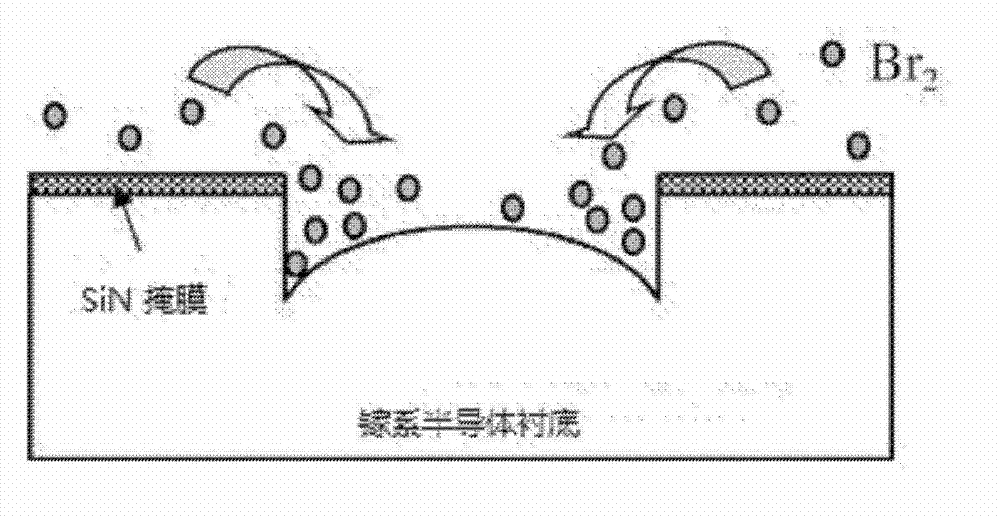
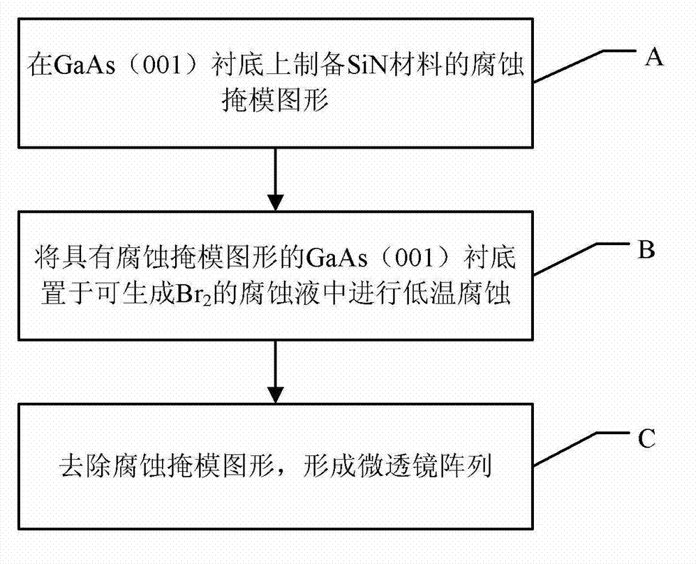
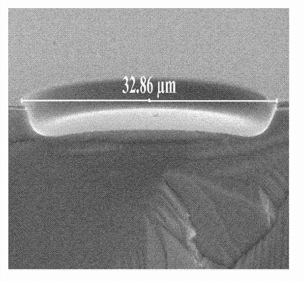
The invention provides a method for manufacturing a micro-lens array. The method comprises the following steps of: manufacturing an etching mask pattern on a gallium-series semiconductor substrate, wherein a plurality of circular-hole arrays are distributed on the etching mask pattern, and the circular-hole arrays correspond to a micro-lens array to be manufactured in position and shape; horizontally putting the gallium-series semiconductor substrate with the etching mask pattern into a corrosive solution which can generate Br2 for carrying out corrosion, wherein the solute of the corrosive solution is a reactant capable of generating Br2, and the solvent of the corrosive solution is an auxiliary solvent with a low melting point; and removing the etching mask pattern from the gallium-series semiconductor substrate to form the micro-lens array. According to the method provided by the invention, due to the use of a low-temperature etchant solution, a lateral under-etching effect in a corrosion process is effectively reduced and the transverse dimension of the micro-lens can be effectively restricted.

Description

technical field [0001] The invention belongs to the technical field of semiconductor materials and devices, and relates to a method for preparing a microlens array on a semiconductor surface by using a diffusion-limited temperature-variable corrosion technique. Background technique [0002] In the field of optoelectronic device technology, improving the collection efficiency of light-emitting devices, compressing the light output angle and stabilizing the light field mode is always the eternal development direction. Different device structures including waveguides, periodic surfaces, and microcavities are widely used in this field, but at the same time, there are different problems such as cumbersome and complex processes, long periodicity, high cost, and low yield. Microlens arrays are increasingly used as a good alternative in more and more scientific fields. The traditional methods of preparing microlens arrays include step-by-step photolithography, femtosecond laser or ...

Claims


Application Information

Patent Timeline
Patent Type & Authority Applications(China)
IPC IPC(8): G02B3/00
Inventor 査国伟喻颖李密峰王莉娟倪海桥贺正宏牛智川
Owner INST OF SEMICONDUCTORS - CHINESE ACAD OF SCI
Why Eureka
Try Eureka