
Light source device and light adjusting control circuit

A technology of dimming control circuit and light source device, applied in the field of diode light source device and its dimming control circuit, can solve the problems of small dimming ratio and the inability of light emitting diode to emit brightness, etc., achieve high dimming ratio and increase dimming The effect of precision

Active Publication Date: 2013-03-06
HOLTEK SEMICON
View PDF2 Cites 5 Cited by
  • Summary
  • Abstract
  • Description
  • Claims
  • Application Information

AI Technical Summary

Problems solved by technology

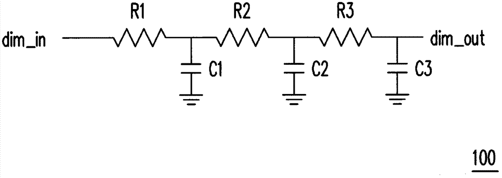
Since the dimming circuit 100 has a cut-off frequency limitation, when the frequency of the dimming signal dim_in exceeds the cut-off frequency, the driving signal dim_out generated by the dimming circuit 100 will be affected, so that the light emitting diode cannot emit the expected brightness.
In addition, the dimming circuit 100 also has the problem of a small dimming ratio (the dimming ratio is about 100:1)

Method used


Image

  • Light source device and light adjusting control circuit
  • Light source device and light adjusting control circuit
  • Light source device and light adjusting control circuit

Examples


Embodiment Construction

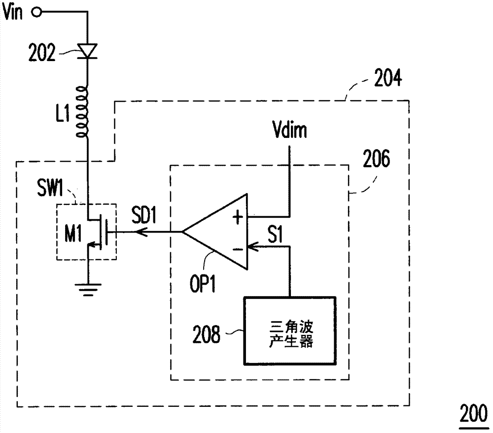
[0049] figure 2 It is a schematic diagram of a light source device according to an embodiment of the present invention. Please refer to figure 2 , the light source device 200 includes a light emitting diode unit 202 , an inductor L1 and a dimming module 204 . The LED unit 202 is coupled between an input voltage Vin and the inductor L1 , the inductor L1 is coupled between the LED unit 202 and the dimming module 204 , and the dimming module 204 is used to adjust the brightness of the LED unit 202 . Further, the dimming module 204 may include a switch unit SW1 and a dimming control circuit 206 . In this embodiment, the switch unit SW1 is implemented by a transistor M1, but it is not limited thereto. The drain of the transistor M1 is coupled to the inductor L1 , the source of the transistor M1 is coupled to ground, and the gate of the transistor M1 is coupled to the dimming control circuit 206 .

[0050] The dimming control circuit 206 is used for generating a driving signal...


PUM


Abstract

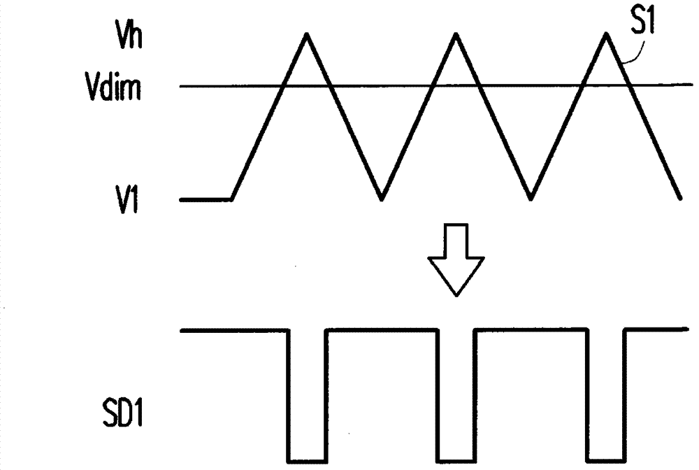
The present invention discloses a light source device and a light adjusting control circuit. The light adjusting control circuit comprises a triangular wave generator and a comparator. The triangular wave generator is used for generating a triangular wave signal. The comparator is used for comparing the triangular wave signal and a light adjusting signal to generate a driving signal. By adopting the light source device and the light adjusting control circuit, high light adjusting and large light adjusting frequency scope can be provided.

Description

technical field [0001] The invention relates to a light source device and its dimming control circuit, and in particular to a diode light source device and its dimming control circuit. Background technique [0002] Light Emitting Diodes (LEDs) are small in size, power-saving and durable, and as the technology matures, the price drops. Recently, products using LEDs as light sources are becoming more and more popular. And with the technological trend of energy saving and carbon reduction, light-emitting diodes have gradually become a new generation of light sources. Light-emitting diodes have low operating voltage, can actively emit light, and have a certain brightness. The brightness can be adjusted by voltage or current. At the same time, it has the characteristics of impact resistance, vibration resistance, and long life (100,000 hours). Therefore, light-emitting diodes are widely used in various terminal equipment, from automotive headlights, traffic lights, text displays...

Claims


Application Information

Patent Timeline
IPC IPC(8): H05B37/02
CPCY02B20/346
Inventor 苏玉昆
Owner HOLTEK SEMICON
Learn More