Slow wave structure of folding frame

A slow-wave structure, folding frame technology, applied in the direction of the circuit components of the transit time type electron tube, can solve the problems of limited application development, small coupling impedance of the traveling wave tube, etc., achieve high coupling impedance value, improve gain and efficiency. Effect

Inactive Publication Date: 2013-03-06
UNIV OF ELECTRONICS SCI & TECH OF CHINA
View PDF3 Cites 12 Cited by
  • Summary
  • Abstract
  • Description
  • Claims
  • Application Information

AI Technical Summary

Problems solved by technology

However, the coupling impedance of the symmetrical double V-shaped microstrip slow-wave structure traveling wave tube is small, which limits its application development.

Method used


Image

  • Slow wave structure of folding frame
  • Slow wave structure of folding frame
  • Slow wave structure of folding frame

Examples


Embodiment Construction

[0021] specific implementation plan

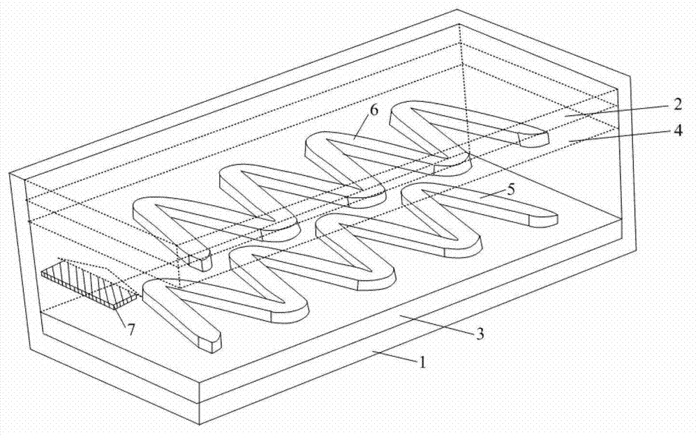
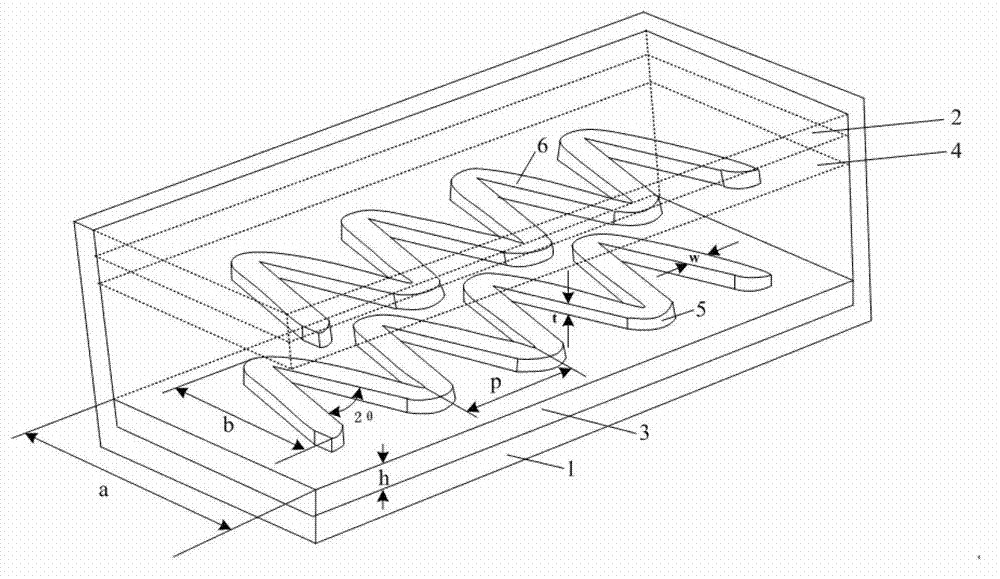
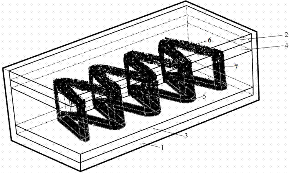
[0022] A folded-box slow-wave structure, such as image 3 As shown, it includes a lower metal base plate 1 and an upper metal base plate 2, the shape and size of the lower metal base plate 1 and the upper metal base plate 2 are the same and parallel to each other; the upper surface of the lower metal base plate 1 has a lower dielectric layer 3, and the upper metal base plate The lower surface of 2 has an upper dielectric layer 4, and the dielectric material and thickness of the lower dielectric layer 3 and the upper dielectric layer 4 are the same; the upper surface of the lower dielectric layer 3 has a lower metal microstrip line 5, and the lower surface of the upper dielectric layer 4 There is an upper metal microstrip line 6; the lower metal microstrip line 5 and the upper metal microstrip line 6 have the same line width, are periodically folded, and are mirror symmetrical to each other; each of the lower metal microstrip line 5 A fold...


PUM


Abstract

The invention relates to a slow wave structure of a folding frame, and the structure belongs to the technical field of microwave electric vacuum devices. The structure comprises an upper metal bottom plate and a lower metal bottom plate (2 and 1) which have the same shape and size and are in parallel with each other; medium layers (3 and 4) are respectively arranged on the opposite surfaces of the upper metal bottom plate and the lower metal bottom plate; metal microstrip lines (5 and 6) are respectively arranged on the opposite surfaces of the medium layers (3 and 4); the upper and the lower metal microstrip lines (5 and 6) have the same line width, are respectively folded periodically, and are mutually in mirror symmetry; and folding top points which correspond to the upper and the lower metal microstrip lines (5 and 6) are connected by metal connecting wires (7). Compared with the existing slow wave structure of a symmetric double V-shaped microstrip line, according to the slow wave structure of the folding frame, the inside of a whole working frequency band is provided with a higher coupling impedance value, so that the gain and the efficiency of a traveling wave tube can be further improved. Meanwhile, the manufacturing of the slow wave structure of the folding frame can be realized through a microfabrication technology, and the structure has wide application prospect.

Description

technical field [0001] The invention belongs to the technical field of microwave electric vacuum devices, and relates to traveling wave tube amplifiers. Background technique [0002] Traveling wave tubes have the incomparable advantages of broadband, high gain and low noise and other electric vacuum devices, and are widely used in radar, communication, microwave remote sensing, guidance and electronic countermeasures and other fields. With the development of modern microwave electronic technology, aerospace engineering and military equipment have put forward higher requirements for broadband, high efficiency and miniaturization of millimeter wave sources. However, compared with the existing solid-state sources, although the traveling wave tube has advantages in high power and wide frequency band, it is bulky and has a high operating voltage. As the core component of the TWT, the slow-wave structure directly affects the efficiency of the beam-wave interaction and the technic...

Claims


Application Information

Patent Timeline
Patent Type & Authority Applications(China)
IPC IPC(8): H01J23/24
Inventor 魏彦玉郭彍徐进殷海荣宫玉彬唐涛黄民智王文祥
Owner UNIV OF ELECTRONICS SCI & TECH OF CHINA
Why Eureka
Try Eureka