
Optical fiber irradiation device

A technology for illuminating devices and optical fibers, which is applied to lighting devices, light guides of lighting devices, components of lighting devices, etc., can solve the problems of lens position shift, large tolerance of packaging substrate, and the need for cooling to reduce luminous efficiency.

Inactive Publication Date: 2013-03-06
USHIO DENKI KK
View PDF2 Cites 7 Cited by
  • Summary
  • Abstract
  • Description
  • Claims
  • Application Information

AI Technical Summary

Problems solved by technology

For example, as an LED light source, cooling is required in order to avoid the reduction of the luminous efficiency of the LED element. The substrate itself tends to have large tolerances, so when the optical fiber is positioned relative to, for example, the LED substrate on which the LED package is placed, the distance between the LED light source and the light incident end face of the optical fiber will vary.
In this way, if the distance between the LED light source and the light incident end face of the optical fiber varies, the amount of light incident on the optical fiber will vary and the light collection efficiency on the lens will change, making it impossible to effectively use the light from the LED light source.
[0008] In addition, in the structure in which the light radiated from the LED light source is condensed by a glass lens or the like and injected into an optical fiber, the above-mentioned problems also arise due to, for example, the positional deviation of the lens.
[0009] On the other hand, in order to avoid this kind of problem, it is also considered to arrange the optical fiber and the LED light source in contact with each other. However, because the optical fiber is sometimes replaced according to the application, in the device of this structure, it is easy to cause the incident light to be caused by the light emitted by the optical fiber. The problem of attenuation caused by damage to the input end face

Method used


Image

  • Optical fiber irradiation device
  • Optical fiber irradiation device
  • Optical fiber irradiation device

Examples


Embodiment Construction

[0051] Hereinafter, embodiments of the present invention will be described in detail.

[0052] The optical fiber irradiation device of the present invention has an optical fiber light source mechanism that condenses light from an LED light source through a lens and injects it into an optical fiber, and guides the light through the optical fiber to irradiate the light in spots.

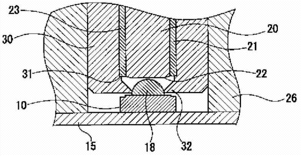
[0053] figure 1 It is an explanatory sectional view showing a schematic structure of an example of an optical fiber light source mechanism in the optical fiber irradiation device of the present invention, figure 2 will be figure 1 An enlarged cross-sectional view showing an enlarged portion of the fiber optic light source mechanism shown.

[0054] This optical fiber light source mechanism has an LED substrate 15, an LED light source arranged on one side of the LED substrate 15, a lens 18 for converging light emitted from the LED light source, and a lens 18 for guiding light from the LED light source...


PUM


Abstract

The subject of the present invention is to provide an optical fiber irradiation device capable of effectively using the light beam from an LED light source to irradiate with sufficient illuminance. To solve the problem, the present optical fiber irradiation device is provided with an optical fiber light source mechanism. The optical fiber light source mechanism is configured in such a manner that an optical fiber is interfaced with a spacer, existed between the optical fiber and a lens, via a state that an optical fiber base mounted on an LED substrate is not restricted, and a light incidence terminal face is opposite to the lens in front of the LED light source mounted on the LED substrate. The optical fiber is fixed to the optical fiber base in a state that the spacer abuts against the front of the LED light source or the lens. As a result, a structure is provided to regulate the separated distance between the front of the LED light source and the light incidence terminal face of the optical fiber.

Description

technical field [0001] The present invention relates to, for example, an optical fiber irradiation device that irradiates an object to be irradiated in point form with ultraviolet light from an LED light source via an optical fiber. Background technique [0002] For example, light irradiation treatment is performed to cure adhesives, paints, inks, and resists that are sensitive to ultraviolet light (wavelength) by using ultraviolet light in the range of 300nm to 400nm with a wavelength centered at 365nm (hardened) or dried, or conversely melted or softened, etc. [0003] In such light irradiation processing, it is often required to irradiate minute areas with ultraviolet light, for example, in the bonding of pickup lenses for optical discs and the bonding of electronic components to substrates. As the ultraviolet light irradiation device that is used for carrying out this kind of light irradiation treatment, the device of the following structure is known: for example, make ...

Claims


Application Information

Patent Timeline
Patent Type & Authority Applications(China)
IPC IPC(8): F21S2/00F21V8/00F21V19/00F21V17/00F21Y101/02
CPCF21V2200/10G02B6/0005H01L33/00
Inventor 松岛竹夫村上悟司
Owner USHIO DENKI KK
Learn More