Eureka AIR delivers breakthrough ideas for toughest innovation challenges, trusted by R&D personnel around the world.

Exhaust heat recovery device of textile printing and dyeing forming machine

A waste heat recovery device, textile printing and dyeing technology, applied in the direction of heat exchanger types, indirect heat exchangers, fixed conduit components, etc., can solve problems such as air pollution, increased production costs of enterprises, energy loss, etc., to extend the contact time, prolong Traveling distance and the effect of improving heat exchange efficiency

Active Publication Date: 2013-02-27
ZHANGJIAGANG DATANG TEXTILE PROD
View PDF6 Cites 3 Cited by
  • Summary
  • Abstract
  • Description
  • Claims
  • Application Information

AI Technical Summary

Problems solved by technology

Generally, the hot air temperature required by the setting machine is about 200°C, and the exhaust gas discharge temperature of the setting machine is also about 170°C, which contains rich heat energy. If the heat energy is not recovered, it will cause significant energy loss and waste, resulting in the production cost of the enterprise. increase, and the current heat recovery measures are to directly heat the fresh air to 130°C again. This kind of heating generally uses heat pipes for heat transfer, and then sends it to the setting machine for recycling. At the same time, 130 The exhaust gas at ℃ is directly discharged, and the exhaust gas has not been treated, which is easy to cause air pollution

Method used


Image

  • Exhaust heat recovery device of textile printing and dyeing forming machine

Examples


Embodiment Construction

[0017] The present invention will be described in further detail below through specific examples.

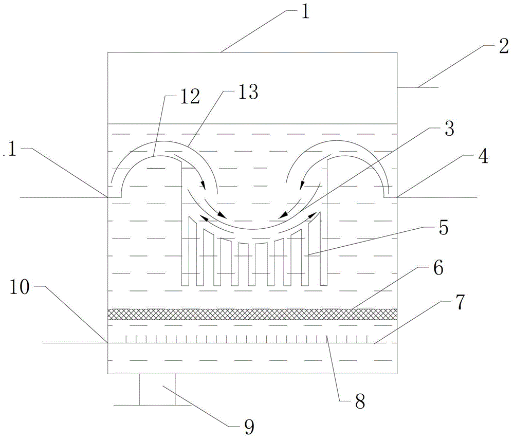
[0018] like figure 1 As shown, a recovery device for exhaust gas waste heat of a textile printing and dyeing setting machine, a recovery pool 1, the recovery pool 1 is equipped with an air washing heat transfer fluid, the bottom of the recovery pool 1 is provided with an exhaust gas inlet 10, and the top is provided with an exhaust gas outlet 2, the recovery pool 1 1 is provided with a coil, one end of the coil protrudes from the recovery tank 1 to form a water inlet 11, and the other end protrudes from the recovery tank 1 to form a water outlet 4, the waste gas inlet 10 is connected to the intake pipeline, and the waste gas outlet 2 is connected to the Gas line, the bottom of recovery tank 1 is provided with drain port 9, and this drain port 9 can also be used as liquid filling port, certainly, also can open another liquid filling port on recovery tank 1.

[0019] Wherein, the...


PUM


Abstract

The invention discloses an exhaust heat recovery device of a textile printing and dyeing forming machine. The device comprises a recovery pool, wherein a gas-washing heat-conducting liquid is arranged in the recovery pool, a waste gas inlet is arranged at the bottom of the recovery pool, a waste gas outlet is arranged at the top of the recovery pool, a coil is arranged in the recovery pool, one end of the coil extends out of the recovery pool to form a water inlet, the other end of the coil extends out of the recovery pool to form a water outlet, the waste gas inlet is connected to a gas inlet pipeline and the waste gas outlet is connected to a gas outlet pipeline. By the aid of the device, the waste gas can be subjected heat recovery further, harmful substances in waste gas can be cleaned, the heat recovery can be improved, and the exhausted waste gas meet environment protection requirements.

Description

technical field [0001] The invention relates to the field of placed printing and dyeing, in particular to a device for recovering waste gas waste heat of a textile printing and dyeing setting machine. Background technique [0002] In the textile industry, the printing and dyeing setting machine is the main processing equipment and one of the energy-consuming equipment. It is a device that dries and finishes the fabric with heated air to set it. Generally, the hot air temperature required by the setting machine is about 200°C, and the exhaust gas discharge temperature of the setting machine is also about 170°C, which contains rich heat energy. If the heat energy is not recovered, it will cause significant energy loss and waste, resulting in the production cost of the enterprise. increase, and the current heat recovery measures are to directly heat the fresh air to 130°C again. This kind of heating generally uses heat pipes for heat transfer, and then sends it to the setting m...

Claims


Application Information

Patent Timeline
Patent Type & Authority Applications(China)
IPC IPC(8): F28D1/06
Inventor 唐利刚
Owner ZHANGJIAGANG DATANG TEXTILE PROD
Why Eureka
Eureka Blog
Learn More