
Mechanical spiral door bolt mechanism for safe box and cabinet

A safe and mechanical technology, applied in door/window accessories, building structure, handle connection, etc., can solve the problems of troublesome operation and assembly, many parts, etc., and achieve the effect of increasing processing cost, small size and fast speed

Inactive Publication Date: 2013-02-27
宁波大榭开发区格林尼森保险箱有限公司
View PDF5 Cites 11 Cited by
  • Summary
  • Abstract
  • Description
  • Claims
  • Application Information

AI Technical Summary

Problems solved by technology

[0003] Chinese Patent No. 201020695659.0 "A Rotating Mechanism for Safe Cabinet Door Locking" discloses a locking rotating mechanism with good anti-prying performance, but it has many parts and troublesome operation and assembly. The teeth and rotating bolts are respectively fixed on the rack plate, the door bolt slide plate and the screw fixing seat, and the rack plate needs to be inserted into the guide hole in the middle of the door bolt slide plate through the push pin on it, so that the rack plate overlaps. Attached in one piece on the side of the deadbolt slide

Method used


Image

  • Mechanical spiral door bolt mechanism for safe box and cabinet
  • Mechanical spiral door bolt mechanism for safe box and cabinet
  • Mechanical spiral door bolt mechanism for safe box and cabinet

Examples


Embodiment Construction

[0012] Embodiments of the present invention will be further described below in conjunction with the accompanying drawings.

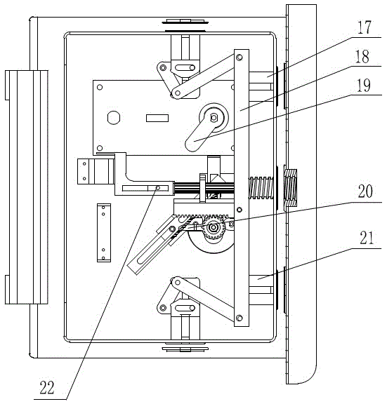
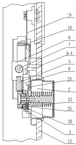
[0013] The rack is a double-groove rack 9, its section is ∟ shape, two waist holes are arranged on the horizontal plane, and upper and lower limit nails 9-2, 9-4 are respectively inserted in the upper and lower waist holes of the double-slot rack. There is a breach 9-3 in the middle of the two vertical junction surfaces, and helical teeth 9-1 are arranged on the upper surface of the vertical surfaces.

[0014] There is a groove in the middle of the upper surface of the rack seat 1, and the upper and lower limit nails are fixed on the groove. The double-groove rack 9 moves in the groove, and the upper and lower limit nails will not fall out. The rack seat 1 is welded obliquely It is fixed on the door panel 12 on the side of the handle base 2-2, and the inclined installation angle of the rack seat matches the inclination angle of the upper helical tooth 9-...


PUM


Abstract

The invention provides a mechanical spiral door bolt mechanism for a safe box and cabinet. The mechanical spiral door bolt mechanism is formed in a way that a gear which is provided with a pulling sheet and is arranged on the handle is engaged with a sliding rack, the sliding rack is matched with a main shaft seat provided with a main shaft, the rack is matched with the rack seat and the pulling sheet, the rack is engaged with the main shaft, the sliding rack is fixedly arranged on a connecting rod, and the handle, the main shaft seat and the rack seat are fixedly arranged on a door plate. The middle links and excessive parts are reduced and omitted, the structure is compact, the size is small, driving and transmission elements are directly and fixedly arranged on the handle, the main shaft seat and the rack seat of the door plate, the transmission interference is avoided, and all parts can be easily manufactured and assembled. The gear and the sliding rack are engaged, the main shaft is driven to move through the connecting rod, the gear drives the double-groove rack to move through the pulling sheet, inclined teeth arranged on the double-groove rack are engaged with the long rack arranged on the main shaft for driving the main shaft to rotate, the connection between the main shaft and a screw sleeve fixedly arranged on the side door frame is firm and reliable, the prying is not easy, the anti-theft performance is good, and safety and reliability in use are realized. The mechanism is arranged on the handle seat and is arranged around the handle seat, the handle is directly held for operation, middle parts do not exist, and the operation is comfortable, easy and labor-saving.

Description

technical field [0001] The invention relates to an important part of a safe cabinet lock, in particular to a mechanical screw bolt mechanism of a safe cabinet. Background technique [0002] With the continuous improvement of people's living standards, the use of safes is increasing, and people have higher and higher requirements for the quality of safes. [0003] Chinese Patent No. 201020695659.0 "A Rotating Mechanism for Safe Cabinet Door Locking" discloses a locking rotating mechanism with good anti-prying performance, but it has many parts and troublesome operation and assembly. The teeth and rotating bolts are respectively fixed on the rack plate, the door bolt slide plate and the screw fixing seat, and the rack plate needs to be inserted into the guide hole in the middle of the door bolt slide plate through the push pin on it, so that the rack plate overlaps. It is connected as a whole on the side of the bolt slide plate. The rack plate is hung on the sliding plate of...

Claims


Application Information

Patent Timeline
Patent Type & Authority Applications(China)
IPC IPC(8): E05B65/52E05B63/14E05B3/00
Inventor 张旭旦
Owner 宁波大榭开发区格林尼森保险箱有限公司
Learn More