Clamp for flattening and processing high-speed power turbine support ring sleeve for gas turbine
A technology for power turbines and gas turbines, which is applied in the direction of manufacturing tools, metal processing equipment, metal processing machinery parts, etc., can solve the problems of difficult manufacturing, lack of suitable fixtures, etc., and achieve the effects of low labor intensity, high efficiency, and simple processing operations.
- Summary
- Abstract
- Description
- Claims
- Application Information
AI Technical Summary
Problems solved by technology
Method used
Image

Examples
specific Embodiment approach 1
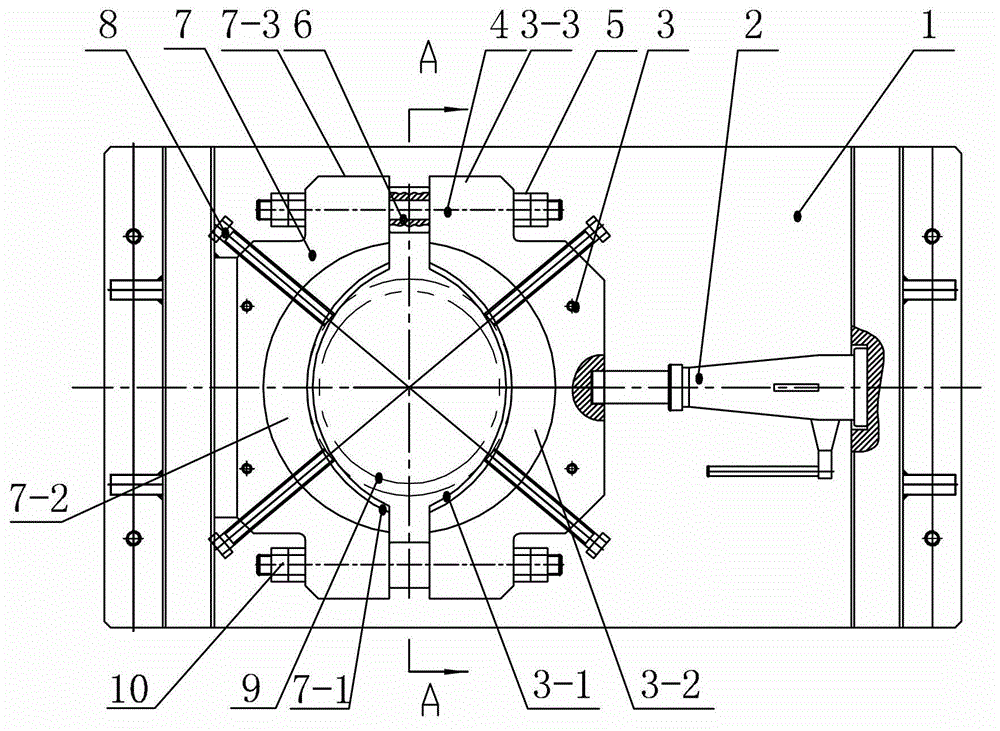
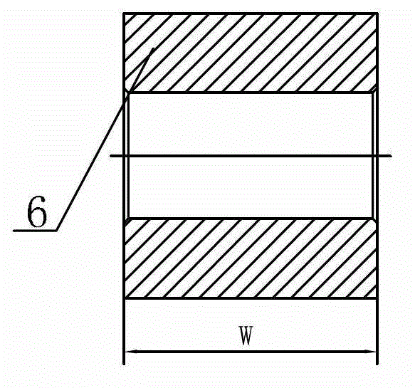
[0007] Specific implementation mode one: combine figure 1 with figure 2 Describe this embodiment, the fixture of this embodiment comprises bracket 1, screw jack 2, right clamp body 3, positioning block 6, left clamp body 7 and two connectors 10, and bracket 1 is provided with right clamp body 3 and left clamp body Concrete 7, the side wall of the right clamp body 3 has a semicircular arc groove 3-1, and the side wall of the left clamp body 7 has a second semicircular arc groove corresponding to the first semicircular arc groove 3-1. Groove 7-1, the workpiece 9 to be processed is arranged in the limiting groove formed by the first semicircular arc groove 3-1 and the second semicircular arc groove 7-1 and the shape of the workpiece 9 to be processed, right The clamp body 3 and the left clamp body 7 are connected by a positioning block 6 and a connector 10, one end of the screw jack 2 is connected with the support 1, and the other end of the screw jack 2 is connected with the o...
specific Embodiment approach 2
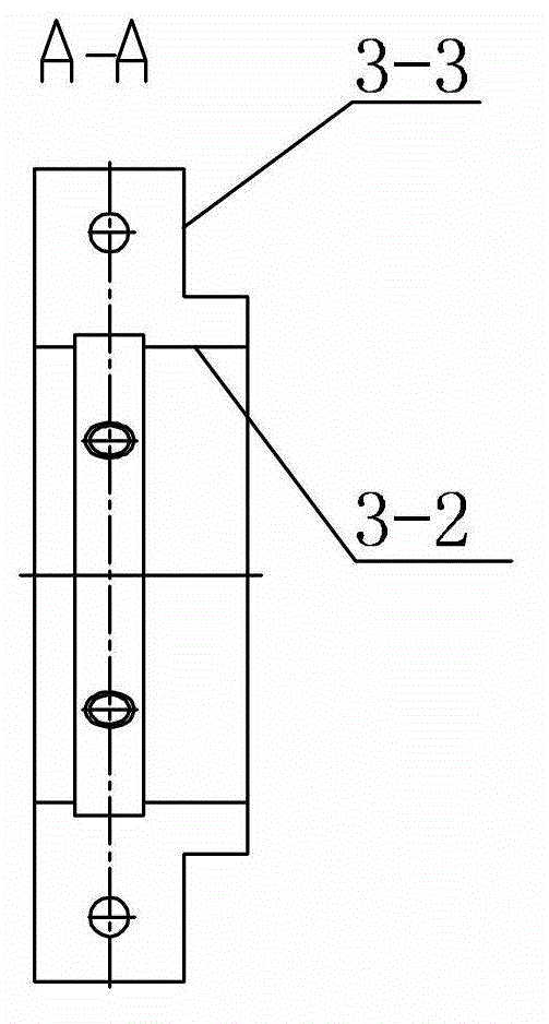
[0008] Specific implementation mode two: combination figure 2 To illustrate this embodiment, the right clamp body 3 of this embodiment is provided with a first boss 3-2, and the left clamp body 7 is provided with a second boss 7-2. Other implementation manners are the same as the specific implementation manner 1.
specific Embodiment approach 3
[0009] Specific implementation mode three: combination figure 1 Describe this embodiment, each connector 10 of this embodiment is a double-ended positioning screw pin 4 and two hex nuts 5, and the upper side wall and the lower side wall of the right clamp body 3 are respectively provided with a first connecting ear 3- 3. The upper side wall and the lower side wall of the left clamp body 7 are respectively provided with a second connecting ear 7-3, and each double-headed positioning screw pin 4 passes through the corresponding first connecting ear 3-3 and positioning block in turn 6 and the second connecting ear 7-3 are fixed by two hex nuts 5 afterward, and this kind of connection method is more convenient. Other implementation manners are the same as the specific implementation manner 1.
PUM
 Abstract
Description
Claims
Application Information
 - Generate Ideas
- Intellectual Property
- Life Sciences
- Materials
- Tech Scout
- Unparalleled Data Quality
- Higher Quality Content
- 60% Fewer Hallucinations
Browse by: Latest US Patents, China's latest patents, Technical Efficacy Thesaurus, Application Domain, Technology Topic, Popular Technical Reports.
© 2025 PatSnap. All rights reserved.Legal|Privacy policy|Modern Slavery Act Transparency Statement|Sitemap|About US| Contact US: help@patsnap.com