Extrusion production device for metal forming of gaily-painted boat
A metal forming and production device technology, applied in forming tools, metal processing equipment, safety equipment, etc., can solve the problems of insufficient extrusion force and high device temperature, and achieve the effect of slowing down the vibration amplitude, not easy to move or shake, and speeding up the speed.
- Summary
- Abstract
- Description
- Claims
- Application Information
AI Technical Summary
Problems solved by technology
Method used
Image
Examples
Embodiment 1
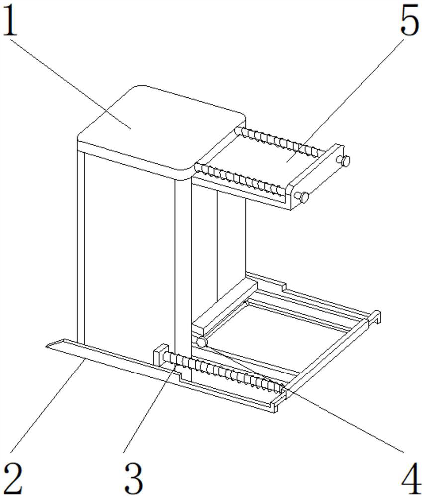
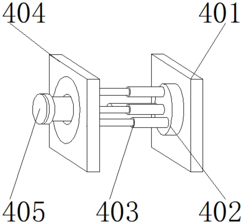
[0027] like Figure 1-6 As shown in the figure, the present invention provides an extrusion production device for metal forming of boats, comprising a main body 1, a pressurizing device 5 is provided on one side of the main body 1, a side plate 2 is provided on the bottom of the main body 1, and the pressurizing device 5 A cooling device 4 is arranged below the cooling device 4, and a shock absorbing device 3 is arranged on one side of the cooling device 4; It is located on one side of the water supply tank 401, and the condensation pipe 403 is located on one side of the water spray assembly 402; One side is detachably connected, a connection hole is provided between the water supply tank 401 and the water spray assembly 402, and one side of the water supply tank 401 is fixedly connected to the other side of the water spray assembly 402 through the connection hole.
[0028] In this embodiment, the cooperating of the condensation pipe 403 and the cooling box 404 enables the me...
Embodiment 2
[0030] like Figure 1-6 As shown, on the basis of Embodiment 1, the present invention provides a technical solution: preferably, the cooling box 404 is located on one side of the condensation pipe 403, the screw sleeve 405 is located on one side of the cooling box 404, and the water spray assembly 402 includes a spray head 4021, pipe network 4022, water flow indicator 4023, alarm valve group 4024, the sprinkler 4021 is located on both sides of the pipe network 4022, the water flow indicator 4023 is located on the inner side of the pipe network 4022, and the alarm valve group 4024 is located at the lower end of the water flow indicator 4023.
[0031] An interface is provided between the condensation pipe 403 and the cooling box 404. The other side of the condensation pipe 403 is fixedly connected to one side of the cooling box 404 through the interface. A thread groove is arranged between the cooling box 404 and the screw sleeve 405. The other side is detachably connected to on...
Embodiment 3
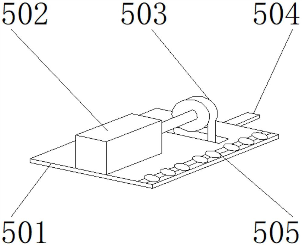
[0034] like Figure 1-6 As shown, on the basis of Embodiment 1, the present invention provides a technical solution: preferably, the booster device 5 includes a mounting base plate 501, a booster 502, a rotating shaft 503, a connecting plate 504, and a blank holder 505. The presser 502 is located at the upper end of the installation base plate 501, the rotating shaft 503 is located at the rear end of the supercharger 502, the connecting plate 504 is located at the rear end of the installation base plate 501, and the edge blanking device 505 is located on one side of the supercharger 502. The edge blanking device 505 It includes a circular cylindrical member 5051, a cylinder core 5052, a steel cylinder 5053, a blank holder 5054, and a piston ring 5055. The cylinder core 5052 is located at the lower end of the circular cylindrical member 5051, and the steel cylinder 5053 is located at one end of the circular cylindrical member 5051. side, the blank holder 5054 is located on one ...
PUM
 Abstract
Description
Claims
Application Information
 - Generate Ideas
- Intellectual Property
- Life Sciences
- Materials
- Tech Scout
- Unparalleled Data Quality
- Higher Quality Content
- 60% Fewer Hallucinations
Browse by: Latest US Patents, China's latest patents, Technical Efficacy Thesaurus, Application Domain, Technology Topic, Popular Technical Reports.
© 2025 PatSnap. All rights reserved.Legal|Privacy policy|Modern Slavery Act Transparency Statement|Sitemap|About US| Contact US: help@patsnap.com


