
Jaw bone density measuring device and jaw bone density measuring method for oral computed tomography (CT) system

A measuring device and dental technology, applied in the field of medical devices, can solve problems such as incomplete reflection of bone density, incapability of quantitative analysis of bone density, increased radiation dose of patients, etc., and achieve low maintenance costs, convenient application, and a wide range of applications

Inactive Publication Date: 2013-02-27
NORTHEASTERN UNIV
View PDF7 Cites 18 Cited by
  • Summary
  • Abstract
  • Description
  • Claims
  • Application Information

AI Technical Summary

Problems solved by technology

[0016] It can be seen from Table 1 that the disadvantage of direct observation of X-ray films lies in the use of two-dimensional plane imaging. The imaging of bone tissue is affected by the superimposition of other parts, and quantitative analysis of bone density measurement cannot be performed. The density depends on the subjective judgment of doctors. For doctors, it is easy to cause large errors in measurement results; the disadvantage of using the reference rod method under X-ray films is that it uses two-dimensional plane imaging, and the imaging of bone tissue is affected by the superimposition of other parts. Although the use of reference rods can reduce the error caused by the doctor's subjective factors, However, no quantitative analysis was carried out, and the specific bone density value could not be obtained. In addition, because there are often metal substances on human teeth, the CT value of metal substances is very large, superimposed on the measurement area, which has a considerable impact on the measurement results; spiral CT The quantitative analysis method is different from the previous two methods. It adopts spiral scanning three-dimensional reconstruction imaging, which is not affected by superimposed information of other parts, and the measurement accuracy is greatly improved. However, this method uses CT value to represent the size of bone density, which cannot fully reflect the True bone density, and this method allows the patient to receive a greatly increased radiation dose
According to the above analysis, there are three main problems in the existing method. First, because the most commonly used X-ray film is a two-dimensional plane imaging, due to the superimposed influence of other human tissues and metal substances, it is impossible to quantify the bone density. Second, under the three-dimensional imaging method, the CT value cannot directly reflect the actual bone density; third, the conventional CT scan causes the patient to receive more radiation dose

Method used


Image

  • Jaw bone density measuring device and jaw bone density measuring method for oral computed tomography (CT) system
  • Jaw bone density measuring device and jaw bone density measuring method for oral computed tomography (CT) system
  • Jaw bone density measuring device and jaw bone density measuring method for oral computed tomography (CT) system

Examples


Embodiment 1

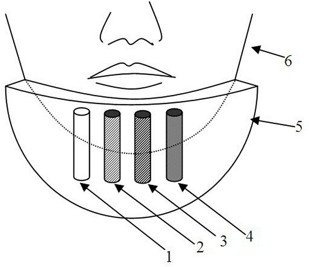
[0049] Such as figure 1 As shown, in this embodiment, there are 4 calibration modules, and the bone tissue equivalent substance selection and bone mineral Ca in each calibration module 10 (PO 4 ) 6 (OH) 2 The atomic number 16.62 is similar to the atomic number 15.83 K 2 HPO 4 As a bone tissue equivalent, formulate K 2 HPO 4 Concentrations were 0 mg / cm 3 , 100 mg / cm 3 , 200 mg / cm 3 , 300 mg / cm 3 K 2 HPO 4 The aqueous solution is sealed and filled in four calibration modules 1, 2, 3, and 4 respectively. In this embodiment, a liquid calibration module that meets the above conditions is used, and a solid calibration module can also be used under other specific implementation conditions.

[0050] Due to the high density of the teeth and jaws themselves, the dynamic range of their CT values ​​in the CT image is large, so in this embodiment, the K of the mixture in each calibration phantom 2 HPO 4 The concentration selection span is large in order to obtain accurate me...

Embodiment 2

[0063] In this embodiment, there are 3 calibration modules, and the bone tissue equivalent material selection and bone mineral Ca in each calibration module 10 (PO 4 ) 6 (OH) 2 The atomic number 16.62 is similar to the atomic number 15.83 K 2 HPO 4 As a bone tissue equivalent, formulate K 2 HPO 4 Concentrations were 50 mg / cm 3 , 150 mg / cm 3 , 250 mg / cm 3 K 2 HPO 4 The aqueous solution is sealed and filled in the four calibration modules 1, 2, and 3 respectively. In this embodiment, a liquid calibration module that meets the above conditions is used, and a solid calibration module can also be used under other specific implementation conditions.

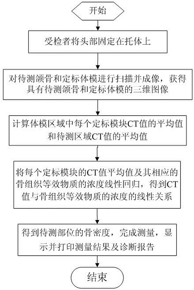
[0064]The method for measuring jaw bone density using the device for measuring jaw bone density used in an oral CT system is the same as that in Example 1.


PUM


Abstract

The invention provides a jaw bone density measuring device and a jaw bone density measuring method for an oral computed tomography (CT) system, and relates to the technical field of medical instruments. The device comprises the oral CT system, a head fixing mechanism, a calibrating phantom and a displaying and measuring device, wherein the head fixing mechanism comprises a rest body and a supporting rod; the calibrating phantom comprises at least three calibrating modules; the calibrating modules are cylindrical plastic containers; water solutions of bone-tissue-equivalent substances are loaded in the containers, and the concentrations of the bone-tissue-equivalent substances in the water solutions in the calibrating modules are different; and the displaying and measuring device is connected with the oral CT system. The device measures the jaw bone density by utilizing a quantitative CT principle and can be used as a head fixing mechanism for a patient being examined during CT scanning to support and fix the head of the patient during the scanning, thereby realizing together imaging of the calibrating phantom and the patient and quantitative measurement of the bone density. By using the method and the device, success rates of surgeries such as dental implantation can be effectively increased and more information is provided for oral CT imaging.

Description

technical field [0001] The invention relates to the technical field of medical devices, in particular to a device and method for measuring jaw bone density used in an oral CT system. Background technique [0002] Before performing dental implant surgery, doctors need to evaluate the jaw bone density at the implant site in order to correctly judge whether surgery is possible and choose the surgical method. At present, doctors mainly use X-rays to judge whether the density of the jaw bone is sparse or hard, but this greatly depends on the experience of the doctor himself. For inexperienced doctors, it is easy to make a misjudgment, resulting in the failure of the operation. [0003] Oral X-ray computed tomography system (oral CT) is the most promising and practical device in the current oral cranial imaging equipment. The application of oral CT has brought revolutionary changes to the diagnosis and treatment in the clinical field of oral cavity and head. Variety. In recent y...

Claims


Application Information

Patent Timeline
Patent Type & Authority Applications(China)
IPC IPC(8): A61B6/03A61B6/14A61B6/51
CPCA61B6/583
Inventor 康雁陈晓朝孝大宇
Owner NORTHEASTERN UNIV
Learn More