
Oil system for heat medium heating furnace

A heating furnace and oil system technology, applied in fluid heaters, lighting and heating equipment, etc., can solve the problems of oil quality deterioration, environmental pollution, etc., and achieve the effect of protecting oil quality

Inactive Publication Date: 2013-02-20
胡顺林
View PDF0 Cites 1 Cited by
  • Summary
  • Abstract
  • Description
  • Claims
  • Application Information

AI Technical Summary

Problems solved by technology

[0005] In this kind of open expansion system, the oil in the expansion tank is connected to the oil return pipe, and the temperature is relatively high, while the heat transfer oil with high temperature in the expansion tank directly contacts the outside air through the vent pipe of the oil storage tank, so that the oil quality deteriorates rapidly, and at the same time The discharge of hot oil vapor has caused environmental pollution

Method used


Image

  • Oil system for heat medium heating furnace
  • Oil system for heat medium heating furnace
  • Oil system for heat medium heating furnace

Examples


Embodiment Construction

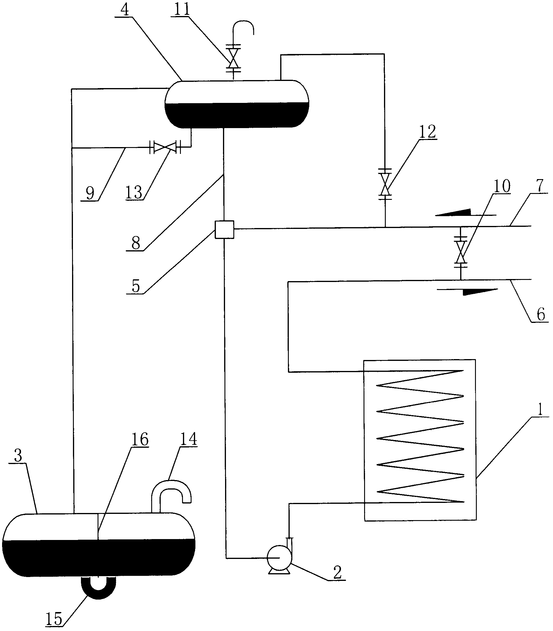
[0016] Such as figure 1 As shown, the oil system of the heat medium heating furnace of the present invention includes the heat medium heating furnace 1, the circulating oil pump 2, the oil storage tank 3, the expansion tank 4, the oil delivery pipe 6, the oil return pipe 7, the oil return pipe 7 and the suction port of the circulation pump 2 The outlet of the circulation pump 2 is connected to the inlet of the heat medium heating furnace 1, the outlet of the heat medium heating furnace 1 is connected to the oil delivery pipe 6, the expansion tank 4 is located at the highest point of the system, the oil storage tank 3 is located at the lowest point of the system, and the oil return pipe The highest point of 7 is provided with an oil-gas separator 5, and the bottom of the expansion tank 4 is provided with an expansion pipe 8, and the expansion pipe 8 is connected to the outlet of the oil-gas separator 5, and an overflow pipe 17 is arranged on the top of the expansion tank 4 to be...


PUM


Abstract

The invention discloses an oil system for a heat medium heating furnace. The oil system comprises the heat medium heating furnace, a circulating pump, an oil storage tank, an expansion tank, an oil supply pipe and an oil returning pipe. The oil returning pipe is connected with a suction port of the circulating pump, an outlet of the circulating pump is connected with an inlet of the heat medium heating furnace, an outlet of the heat medium heating furnace is connected with the oil supply pipe, the expansion tank is located at the highest position of the system, the oil storage tank is located at the lowest position of the system, the highest position of the oil returning pipe is provided with an oil-gas separator, the bottom of the expansion tank is provided with an expansion pipe, the expansion pipe is connected with an outlet of the oil-gas separator, an overflow pipe is arranged above the expansion tank to be connected with the oil storage tank, and a ventilating opening is additionally arranged on the upper portion of the oil storage tank. The oil system is characterized in that a partition plate separating the left side from the right side is arranged on the cross section in the middle of the oil storage tank, and the bottom of the oil storage tank is provided with a U-shaped communicating pipe which enables two chambers on the left side and the right side of the partition plate to be communicated. Hot oil steam is separated by cold oil on the left side of the oil storage tank, does not contact with the outside atmosphere, and is not discharged out. After cooling, the oil steam returns to the oil storage tank, oiliness can be fully protected, and air is not polluted.

Description

technical field [0001] The invention relates to an oil system, in particular to an oil system of a heat medium heating furnace. Background technique [0002] In industrial production, indirect heating is widely used. Most of the traditional indirect heating methods use water and steam as the medium. , when the temperature reaches 200°C, the pressure will reach 4MPa. Due to the high risk brought by high pressure, when the temperature required by the heating equipment is very high, if steam is used as the medium, in order to ensure safety, the investment and use cost of equipment will be greatly increased. In contrast, when the temperature reaches 300°C, the vapor pressure of the heat transfer oil is lower than 0.05MPa, so the heat medium heating furnace has been used more and more. The principle is to use heat-conducting oil as a medium for transferring heat. First, heat the low-temperature oil through a heating furnace, then use pipelines to transport high-temperature oil ...

Claims


Application Information

Patent Timeline
Patent Type & Authority Applications(China)
IPC IPC(8): F24H9/00
Inventor 胡顺林
Owner 胡顺林
Learn More