
Communication system and communication method for underground logging instrument bus

A communication system and logging instrument technology, applied in the bus network, borehole/well components, measurement, etc., can solve the problems of large instrument modification range, small equipment flow rate, and high requirements for application personnel, so as to simplify development, increase speed, Effects of Simplifying Coupling and Dependencies

Inactive Publication Date: 2013-02-13
CNPC GREATWALL DRILLING ENG
View PDF3 Cites 0 Cited by
  • Summary
  • Abstract
  • Description
  • Claims
  • Application Information

AI Technical Summary

Problems solved by technology

These technologies have the following disadvantages, such as: each instrument needs to be set in sequence, which causes great inconvenience to R&D and testing, and has high requirements for the application personnel on the well; the degree of coupling with the ground system is too high, and all data messages are integrated by the ground equipment. Adding new instruments requires re-opening the ground control equipment; currently, the equipment developed on this basis has a small flow rate, only tens of K to hundreds of K, and cannot support the new generation of logging tools; the system architecture makes the entire logging system The coupling degree of the software architecture is very high, and the addition of new instruments leads to a large modification of the network management software; there are many manufacturers of instruments now, if new instruments are to be added to this architecture, the modification of the instruments will be very large, and the workload will be very heavy

Method used


Image

  • Communication system and communication method for underground logging instrument bus
  • Communication system and communication method for underground logging instrument bus
  • Communication system and communication method for underground logging instrument bus

Examples


Embodiment Construction

[0025] In order to make the technical solution of the present invention more clear and definite, the present invention will be described in more detail below with reference to the accompanying drawings and in combination with specific embodiments. The drawings are schematic and not necessarily drawn to scale, like reference numerals referring to like parts throughout.

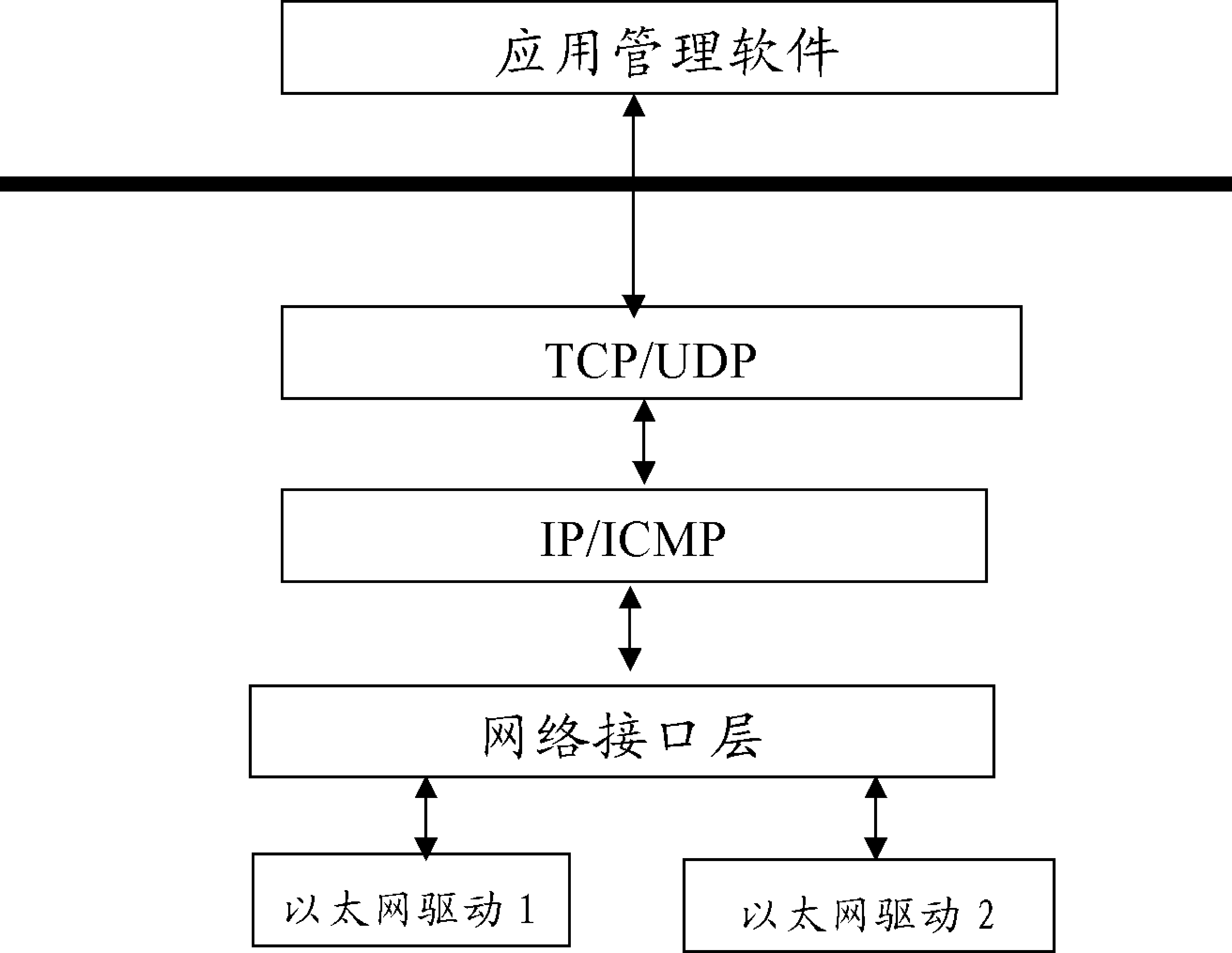
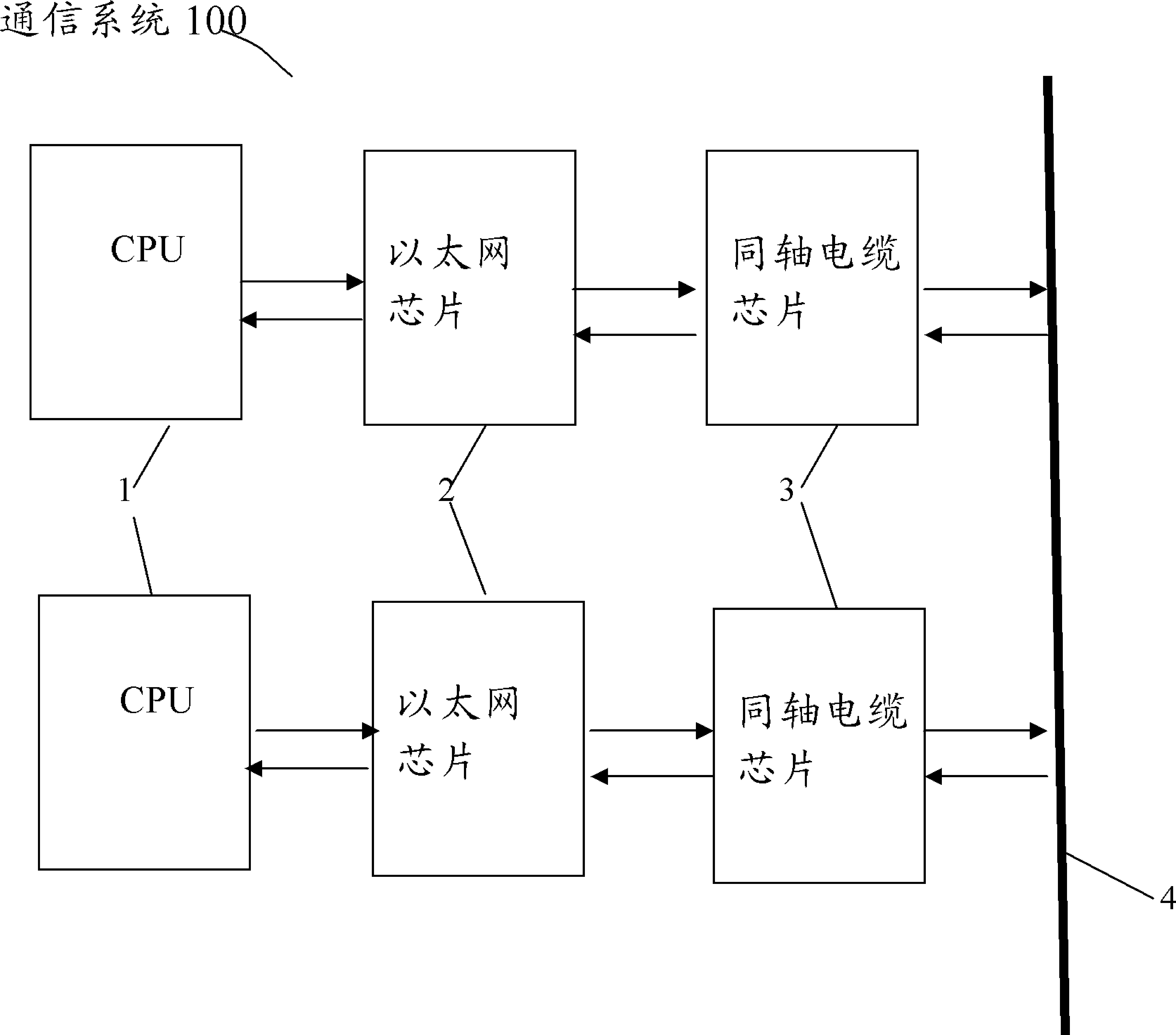
[0026] FIG. 1 is a schematic diagram showing a schematic configuration of a communication system of the present invention. The communication system 100 of the present invention adopts Ethernet technology in hardware architecture, and utilizes a communication mode of a central processing unit (hereinafter referred to as CPU) 1 + Ethernet chip 2 + coaxial cable chip 3 . In addition, although the number of each component is specifically shown in the figure, it is only illustrative here and is not limited thereto. The number of each component only needs to be one or more. The above-mentioned communication method en...


PUM


Abstract

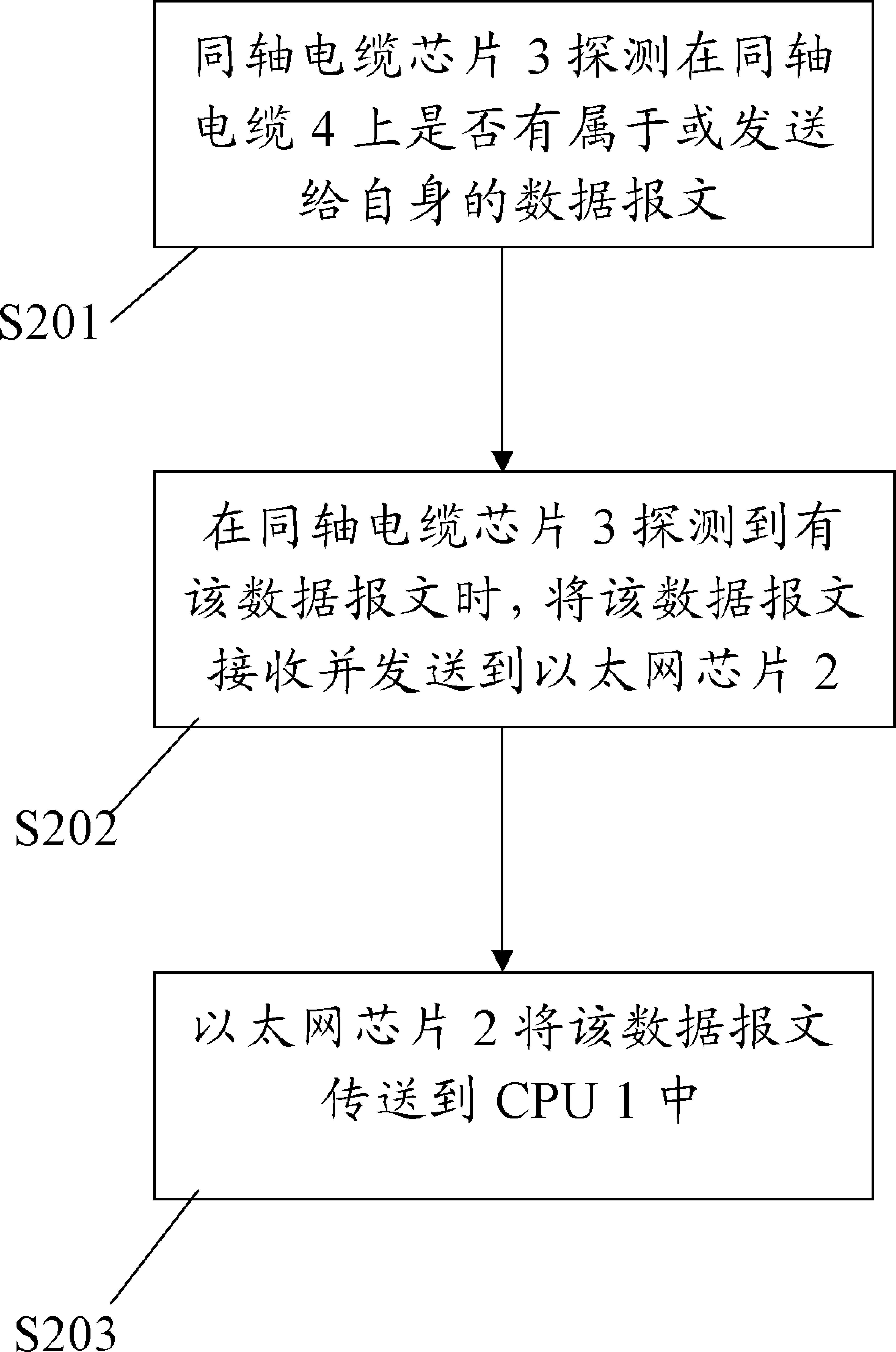
The invention provides a communication system and a communication method for an underground logging instrument bus. The communication system is provided with a coaxial cable and an underground logging instrument, and also comprises a central processing unit, an Ethernet chip connected to the central processing unit and a coaxial cable chip connected between the Ethernet chip and the coaxial cable. When receiving a transmitted message from the central processing unit, the Ethernet chip transmits the transmitted message to the coaxial cable by calling the coaxial cable chip; and when detecting a data message belonging to the coaxial cable chip or transmitted to the coaxial cable chip on the coaxial cable, the coaxial cable chip receives and transmits the data message to the Ethernet chip, and the Ethernet chip transmits the data message to the central processing unit. Coupling and relevancy between equipment can be simplified, the equipment is modularized, and a bus data transmission platform is established, so that instruments of each manufacturer can be easily compatible.

Description

technical field [0001] The present invention relates to a communication system and a communication method, in particular to a communication system and a communication method used in a logging downhole instrument bus. Background technique [0002] Geophysical well logging or petroleum well logging, referred to as well logging for short, is a method of measuring geophysical parameters using the electrochemical properties, electrical conductivity, acoustic properties, radioactivity and other geophysical properties of rock formations. It belongs to applied geophysical methods (including gravity, magnetic , electricity, seismic, logging). Generally, it can be divided into electrical logging, sonic logging, radioactive logging, formation dip logging, gas logging, formation testing logging, gas drilling logging, etc. according to the detected rock physical properties or detection purposes. All kinds of well logging instruments manufactured by using electric, magnetic, acoustic, th...

Claims


Application Information

Patent Timeline
Patent Type & Authority Applications(China)
IPC IPC(8): H04L12/40E21B47/12
Inventor 陈文轩岳宏图陈文戴光明汪新国裴彬彬
Owner CNPC GREATWALL DRILLING ENG
Learn More