Method for producing a monocrystalline body from a magnetic shape memory alloy

A kind of MSM-, single crystal technology, applied in the direction of material selection, crystal growth, single crystal growth, etc. for magnetostrictive devices, can solve the problems of difficult operation, expensive nucleation crystal cost, etc., to achieve the reduction of scraps, Examining the Effect of Placement Reduction

Active Publication Date: 2013-02-06
ETO MAGNETIC GMBH
View PDF4 Cites 0 Cited by
  • Summary
  • Abstract
  • Description
  • Claims
  • Application Information

AI Technical Summary

Problems solved by technology

But this approach is problematic in several ways; not only are suitable nucleating crystals expensive and difficult to manipulate, especially for industrial manufacturing processes outside of laboratory settings, but such nucleating crystals also require very precise process control in order to achieve the correct nucleation properties (provided the nucleation crystal has alloy-repelling material, the MSM-effect of the produced MSM-element may also have other drawbacks)

Method used


Image

  • Method for producing a monocrystalline body from a magnetic shape memory alloy
  • Method for producing a monocrystalline body from a magnetic shape memory alloy
  • Method for producing a monocrystalline body from a magnetic shape memory alloy

Examples


Embodiment Construction

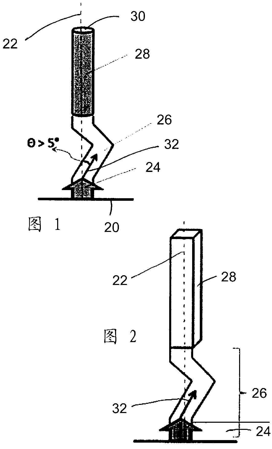
[0022] figure 1 This shows the principle with which the invention can be realized according to a first exemplary embodiment. The figure shows the so-called mold shell for producing single crystals according to the so-called Bridgman method (Bridgman-Verfahren), which mold shell extends perpendicularly from the cold plate 20 along the longitudinal axis (dashed line 22), forming a formation A core region (Ankeimbereich) 24 , a selector region (Selektorbereich) 26 following this nucleation region and a crystal region (Kristallbereich) 28 . The suitably melted alloy material is inserted into the device through the upper opening 30, and the liquid alloy material is then solidified from bottom to top (arrow 32) under the condition of forming a corresponding upwardly moving solidification front, the movement speed of the solidification front is controlled by a suitable Temperature affects reservations.

[0023] figure 1 (akin figure 2 ) shows how the solidification path accord...


PUM

PropertyMeasurementUnit
sizeaaaaaaaaaa
areaaaaaaaaaaa

Abstract

The invention relates to a method for producing an MSM actuator element, having a crystal orientation along a first crystal axis, from a monocrystalline MSM body by introducing a molten alloying material into a molding shell and subsequently solidifying the alloying material, comprising the following steps: providing a molding shell which comprises a nucleation region (24), a selector region (26) and a crystal region (28) and is oriented along a longitudinal axis (22) at least in some sections; introducing the molten MSM alloying material, in particular NiMnGa-based alloying material, into the molding shell without providing a separate nucleation crystal; compacting the MSM alloying material by generating a solidification front moving from the nucleation region across the selector region into the crystal region along a solidification path, wherein the solidification path in the crystal region runs along the longitudinal axis, forms a region which is deflected from the longitudinal axis in the selector region, the maximum deflection of which, relative to the longitudinal axis, is greater than a maximum cross-sectional width in the selector region, and the longitudinal axis (22) has an angular deviation of less than 10 degrees, preferably less than 6 degrees, and more preferably less than 3 degrees, from the first crystal axis, and dividing the solidified MSM alloying material into a plurality of MSM actuator elements.

Description

technical field [0001] The invention relates to a method for producing a single-crystal MSM-body for producing an MSM-actuator, and also to such a single-crystal MSM-body, how it is produced by this method. Background technique [0002] MSM-actuators (also called "MSM-actuators") are generally known in the prior art and utilize the effect that, under the influence of a magnetic field, so-called magnetically controlled shape memory materials (MSM=magnetic Controlled shape memory) to implement an expansion motion (typically in the single-digit percentage range based on the length of each MSM-body along the expansion direction), may be the basis for the drive and may be known in this regard by means of permanent magnets and An alternative to an electromagnet-implemented adjustment element. [0003] Apart from the alloy used (typically NiMnGa-based alloys), the effectiveness of such an MSM actuator or MSM actuator is decisive for the crystallographic orientation along which the...

Claims


Application Information

Patent Timeline
Patent Type & Authority Applications(China)
IPC IPC(8): H01L41/20C30B11/00
CPCC30B11/00C30B11/14B22D23/00C30B29/52H01L41/20H01L41/47H01F1/0308H10N35/85H10N35/01
Inventor M.劳芬伯格E.帕古尼斯A.德雷弗曼L.斯特茨
Owner ETO MAGNETIC GMBH
Why Eureka
Try Eureka