Heat conduction metal core and PCB (Printed Circuit Board) board using same

A heat-conducting metal and PCB board technology, applied in the direction of cooling/ventilation/heating transformation, printed circuit components, etc., can solve the problems of non-grounded heat sink, low production efficiency, complex process, etc., to achieve tight integration, good heat dissipation effect, The effect of simple heat conduction structure

Inactive Publication Date: 2013-02-06
DONGGUAN SHENGYI ELECTRONICS
View PDF4 Cites 0 Cited by
  • Summary
  • Abstract
  • Description
  • Claims
  • Application Information

AI Technical Summary

Problems solved by technology

[0003] 1. On the conventional heat-conducting PCB board, the dielectric constant (Dk) of the conventional heat-conducting material is large, the heat conduction effect is not good and the heat sink is not grounded, resulting in low heat conduction efficiency, and the electrical signal transmission loss and distortion on the PCB board are large;
[0004] 2. The process of laminating and embedding heat-conducting materials is more complicated, and there are disadvantages such as the need to oxidize the PCB board before lamination, and the glue stains on the surface of heat-conducting materials after lamination are difficult to remove, resulting in low production efficiency and low pass rate;
[0005] 3. At present, the method of mechanically inserting straight heat-conducting materials into the slots of the PCB board is adopted. The two bottom surfaces of the heat-conducting materials are parallel and perpendicular to the sides. scrapped

Method used


Image

  • Heat conduction metal core and PCB (Printed Circuit Board) board using same
  • Heat conduction metal core and PCB (Printed Circuit Board) board using same
  • Heat conduction metal core and PCB (Printed Circuit Board) board using same

Examples


Embodiment Construction

[0026] In order to make the technical solution of the present invention more clearly expressed, the present invention will be further described below in conjunction with the accompanying drawings.

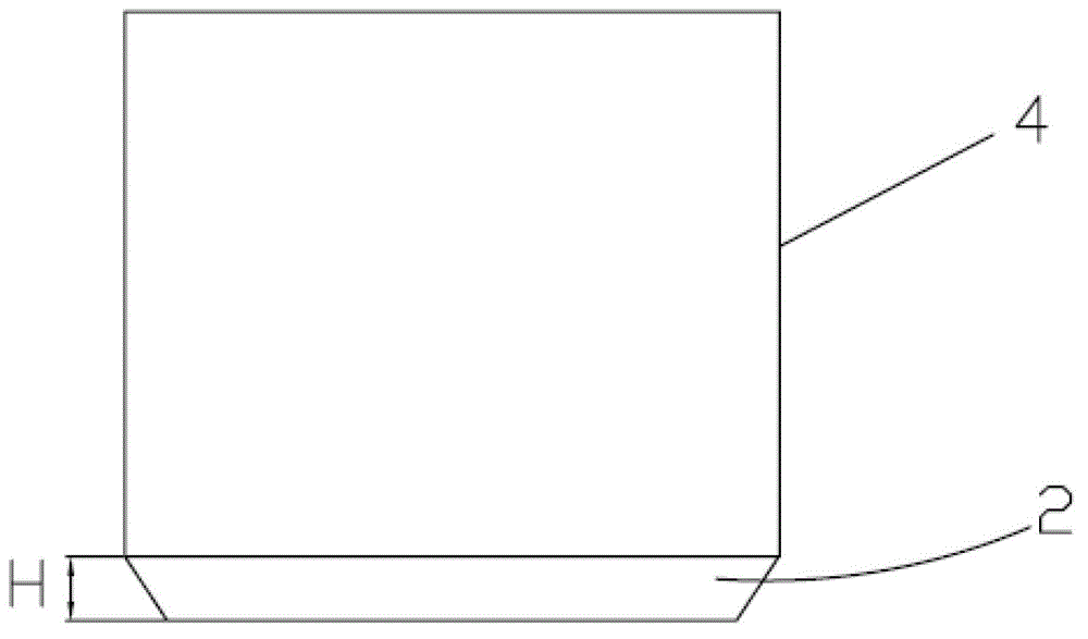
[0027] see figure 1 , the present invention provides a heat-conducting metal core, including a core body 4, and an introduction structure 2 axially extended from the end of the core body 4. .

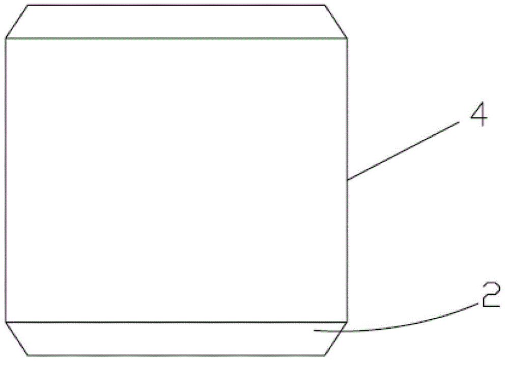
[0028] Wherein, the introduction structure 2 can be arranged at one end or both ends of the core body 4 , and in this embodiment, the introduction structure 2 is only arranged at one end of the core body 4 .

[0029] The longitudinal section of the introduction structure 2 is trapezoidal, that is, the longitudinal section passing through the axis of the core 4 is trapezoidal. The height H of the trapezoid is between 0.2mm and 0.5mm.

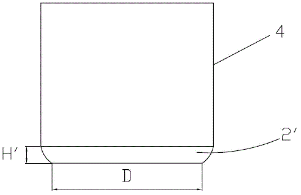
[0030] see figure 2 , is a schematic structural diagram of the second embodiment of the heat-conducting metal core of the present invention. In this embod...


PUM

PropertyMeasurementUnit
Heightaaaaaaaaaa

Abstract

The invention provides a heat conduction metal core and a PCB board using same. The heat conduction metal core comprises a core body and a leading-in structure which is extended from the end part of the core body, wherein the leading-in structure is a cone which is gradually tapered towards the end far from the core body. With the leading-in structure, the heat conduction metal core can be easily pressed to an open slot of the PCB board; moreover, the leading-in structure can be pre-positioned at the top of the open slot of the PCB board without dropping and inclining, so that the heat conduction metal core can be accurately and flatly pressed to the open slot of the PCB board; and besides, the heat conduction metal core is firmly combined with the PCB board without dropping. The heat conduction metal core is pressed on the heat conduction metal core PCB board, simple in the heat conduction structure and good in radiating effects.

Description

technical field [0001] The invention relates to a printed circuit board (PCB) heat conduction technology, in particular to a crimping type heat conduction metal core with a tapered lead-in structure and a PCB board using the heat conduction metal core. Background technique [0002] The existing PCB heat conduction technology and its defects are as follows: [0003] 1. On the conventional heat-conducting PCB board, the dielectric constant (Dk) of the conventional heat-conducting material is large, the heat conduction effect is not good and the heat sink is not grounded, resulting in low heat conduction efficiency, and the electrical signal transmission loss and distortion on the PCB board are large; [0004] 2. The process of laminating and embedding heat-conducting materials is more complicated, and there are disadvantages such as the need to oxidize the PCB board before lamination, and the glue stains on the surface of heat-conducting materials after lamination are difficul...

Claims


Application Information

Patent Timeline
IPC IPC(8): H05K1/02H05K7/20
Inventor 李民善纪成光杜红兵吕红刚
Owner DONGGUAN SHENGYI ELECTRONICS
Why Eureka
Try Eureka