Movable type laser reflection, laser refraction and lens imaging demonstration combined device and using method thereof

A technology of refracting lens and combination device, which is used in educational appliances, instruments, teaching models, etc., can solve problems such as poor experimental results and inability to flexibly form various optical paths, and achieve the effects of simple structure, convenient adjustment, and strong beam intensity.

Active Publication Date: 2013-02-06
曾克夫 +1
View PDF3 Cites 14 Cited by
  • Summary
  • Abstract
  • Description
  • Claims
  • Application Information

AI Technical Summary

Problems solved by technology

Since the beam exit position is fixed, the movement of the beam position is limited, and optical tools such as the lens 805 are fixed through the handle insertion hole 806, which cannot flexibly form various optical paths; and after a beam of light is divided into three beams, one is dimmer than the other, and the experimental results bad

Method used


Image

  • Movable type laser reflection, laser refraction and lens imaging demonstration combined device and using method thereof
  • Movable type laser reflection, laser refraction and lens imaging demonstration combined device and using method thereof
  • Movable type laser reflection, laser refraction and lens imaging demonstration combined device and using method thereof

Examples


Embodiment 1

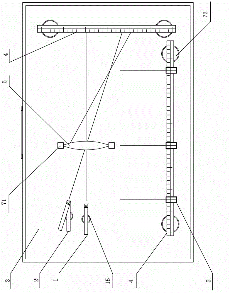
[0061] Embodiment 1: Mobile Laser Reflective Refractive Lens Imaging Demonstration Combination Device I

[0062] Such as figure 1 As shown, the device uses a semiconductor laser emitter I1 capable of emitting one beam of light and a semiconductor laser emitter II2 capable of emitting two beams of light as demonstration light sources, which are installed on the magnetic teaching board 3 through a magnetic base.

[0063] The matching optical assembly is a convex lens 6 equipped with a magnetic base 71, and a straightedge 4 with a magnetic base 72 installed at a right angle is arranged on both sides of the magnetic base 71, and a slidable measurement is arranged on one of the rulers. pointer 5. The combined demonstration device can be used for demonstration of convex lens imaging law.

Embodiment 2

[0064] Embodiment 2: Mobile Laser Reflective Refractive Lens Imaging Demonstration Combination Device II

[0065] Such as Image 6 As shown, the device uses two semiconductor laser emitters I1 capable of emitting a beam of light as a demonstration light source, and is installed on the magnetic teaching board 3 through a magnetic base 15, and the matching optical assembly is equipped with a magnetic base 71 The convex lens 6 has a straightedge 4 with a magnetic base 72 installed at right angles on both sides of the magnetic teaching board 3. This combined demonstration device can be used to measure the focal length of the convex lens for demonstration.

Embodiment 3

[0066] Embodiment 3: Mobile Laser Reflective Refractive Lens Imaging Demonstration Combination Device III

[0067] Such as Figure 7 As shown, the device uses a semiconductor laser emitter I1 capable of emitting a beam of light as a demonstration light source, and is installed on the magnetic teaching board 3 through a magnetic base 15, and the matching optical assembly is a magnetic base 73 A flat mirror 8 and a rotatable optical disc 9 with a magnetic base, the demonstration combination device III is used for the measurement demonstration of the relationship between the rotation angle of the plane mirror and the rotation angle of the outgoing light.

[0068] The first to third embodiments above are just one of the multiple combinations of the mobile laser light reflective refraction lens imaging demonstration combination device of the present invention. According to the needs of the demonstration, there can be many other combinations, which will not be listed here.


PUM


Abstract

A movable type laser reflection, laser refraction and lens imaging demonstration combined device comprises a movable type semiconductor laser transmitter, an optical module, a teaching aid and a magnetic demonstrating board, wherein the optical module and the teaching aid are matched with optical experiments in use. The movable type semiconductor laser transmitter comprises a semiconductor laser transmitter I capable of emitting a beam of light or / and a semiconductor laser transmitter II capable of emitting two beams of light. The bottom of the semiconductor laser transmitter I, magnetic bases are installed at the bottom of the semiconductor laser transmitter II and the bottoms of the optical module and the teaching aid matched with the optical experiments in use. The magnetic demonstrating board is a flat board capable of sucking the magnetic bases. When the device is used, the movable type semiconductor laser transmitter and the optical module and the teaching aid matched with the optical experiments in use are sucked on the magnetic demonstrating board through the magnetic bases and can be moved optionally. The device can perform more than 50 optical experiments including light rectilinear propagation, light reflection, light refraction, lens imaging law, light interference, light diffraction and the like.

Description

technical field [0001] The invention relates to a teaching demonstration device, in particular to a combination device for optical reflection and refraction lens imaging demonstration for teachers' teaching or students' experiments. Background technique [0002] At present, in middle school laboratories, the helium-neon laser assembly 801 used for the demonstration of light reflection and refraction and the demonstration of lens imaging rules is fixed at the lower end of the teaching board, and the light passes through the exit hole 802 and shoots vertically to the three dielectric films fixedly installed at the upper end. On the beam reflector 803, the angle of the outgoing light is changed by turning the reflector angle adjustment knob 804 (see Figure 8 ). Since the beam exit position is fixed, the movement of the beam position is limited, the lens 805 and other optical tools are fixed through the handle insertion hole 806, and various optical paths cannot be flexibly for...

Claims


Application Information

Patent Timeline
IPC IPC(8): G09B23/22
Inventor 曾克夫
Owner 曾克夫
Why Eureka
Try Eureka