
Full-circle integrated upside-down hanging formwork and its erecting and demoulding methods

A formwork and integrated technology, which is applied in earth-moving drilling, hydropower station, wellbore lining, etc., can solve the problems of not being able to seal the exposed and broken surrounding rock in time, greatly affecting the construction progress, and long construction cycle time, etc. Labor conditions, avoidance of direct interference, the effect of low equipment costs

Active Publication Date: 2015-12-02
广汉金达隧道机械有限公司
View PDF3 Cites 0 Cited by
  • Summary
  • Abstract
  • Description
  • Claims
  • Application Information

AI Technical Summary

Problems solved by technology

[0005] If the upside-down concrete construction is carried out according to the existing technology, large-scale combined steel formwork is used for pouring. On the one hand, the construction workload of erecting scaffolding and formwork is large, the construction cycle time is long, and the exposed and broken surrounding rock cannot be closed in time.
Moreover, pouring upside-down concrete with combined steel formwork seriously interferes with the construction of the excavation process of the large well, and has a great impact on the construction progress of the entire project.

Method used


Image

  • Full-circle integrated upside-down hanging formwork and its erecting and demoulding methods
  • Full-circle integrated upside-down hanging formwork and its erecting and demoulding methods
  • Full-circle integrated upside-down hanging formwork and its erecting and demoulding methods

Examples


Embodiment

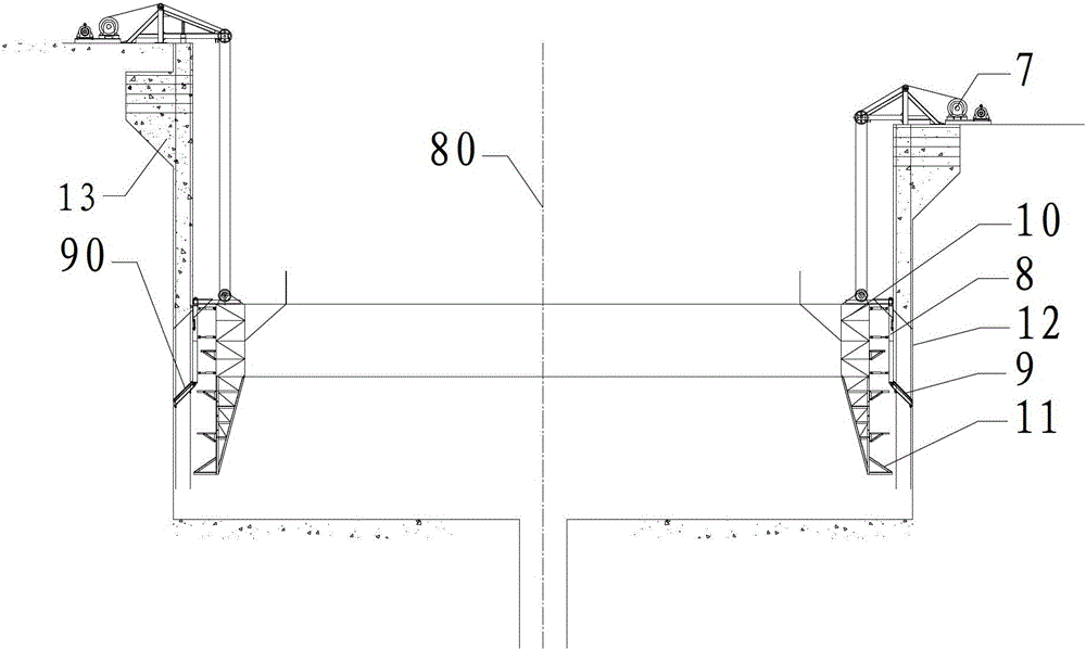
[0047] The surge shaft of a certain power station is an open cylindrical differential type, with an excavation depth of 118m and an excavation diameter of 31m; the permanent structure concrete thickness is 2m, the diameter of the large well after lining is 27m, and the shaft depth is 108m. It is arranged in the middle of a thin ridge with steep terrain on both sides The upper part of about 60m is placed in the strong unloading Class V loose and broken surrounding rock. The surrounding rock lacks self-stability. After excavation, the rock mass around the upper shaft wall is thin and the well-forming conditions are very poor. Under such extremely poor geological conditions, to build a large-section open deep surge tank, the stability of the surrounding rock of the large shaft wall is the key to safe construction. In order to ensure the safety and progress of the construction, the parallel operation method of digging a large well, laying anchor rods and hanging net concrete, and po...


PUM


Abstract

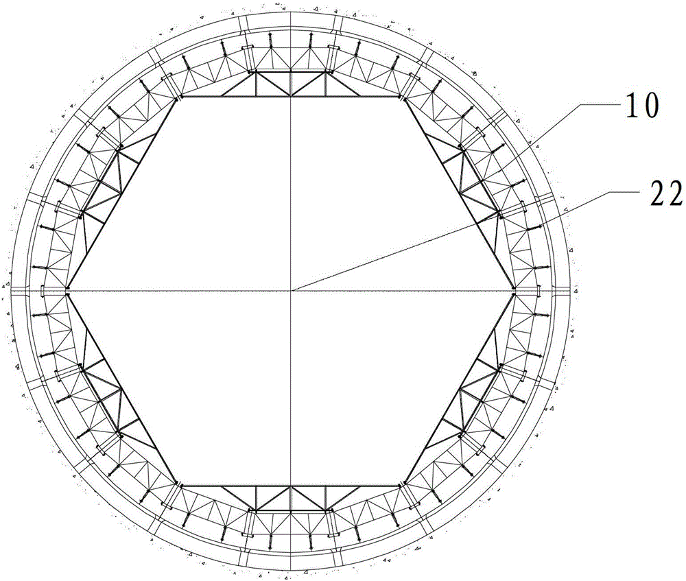
The invention discloses a whole-circle whole invertedly-hanging template which can achieve invertedly-hanging concrete construction and mold-erecting and demolding methods of the template. The construction period is shortened, a template assembly of the template comprises a whole-circle side mold and an inclined plane bottom mold of which a mold surface is a side surface of a round platform, the inclined plane bottom mold is in pin roll connection with the whole-circle side mold, the included angle between a mold surface base line of the inclined plane bottom and an axial line of the whole-circle side mold is an acute angle, reinforcing steel bars of concrete circle layers serve as hanging supports of the inclined plane bottom mold. During mold erecting, the inclined plane bottom mold is in position firstly, a template supporting frame is installed and is connected with a template lifting device on a well head platform, the whole-circle side mold is connected with the template supporting frame, the template lifting device moves, the template supporting frame and the whole-circle side mold are lowered, so that the frame, the whole-circle side mold and the whole-circle side mold are in counterpoint connection, during demolding, the inclined plane bottom mold is lowered firstly and then is in place, then the whole-circle side mold is lowered and detached, by the aid of the template, the concrete construction supporting and the excavation construction are conducted simultaneously, and the template is low in cost, reliable in structure, convenient to operate and rapid in lining speed.

Description

Technical field [0001] The invention relates to a shaft concrete lining forming construction equipment. Background technique [0002] At present, there are two main conventional lining methods for the concrete lining of the surge shaft of the power station: one is to use the combined steel formwork for pouring, and the formwork and erecting are all artificially, and the scaffolding is used to support the formwork. However, this method has a large amount of construction work, long construction cycle time and slow construction progress. The second method is to use the shaft hydraulic sliding form method to pour the lining. The shaft hydraulic sliding form is the more mature method of the pressure regulating shaft lining at present. [0003] According to the structure type and layout characteristics of the shaft, its hydraulic sliding form system is mainly composed of formwork system, operating platform system, hydraulic lifting system and auxiliary system. Based on the pre-cast bot...

Claims


Application Information

Patent Timeline
Patent Type & Authority Patents(China)
IPC IPC(8): E21D5/12E02B9/00
CPCY02E10/22Y02E10/20
Inventor 杨党荣周平刘仲伟秦富华
Owner 广汉金达隧道机械有限公司
Learn More