
Pipeline leakage on-line monitoring device and method based on f fiber temperature detection

A technology of pipeline leakage and optical fiber temperature measurement, which is applied in the direction of measuring devices, pipeline systems, thermometers, etc., can solve the problems of inaccurate positioning, high false alarm rate, and great influence on monitoring results, so as to improve response time and reduce false alarms rate, wide coverage

Inactive Publication Date: 2013-01-30
E TECH ENERGY TECH DEV CORP
View PDF4 Cites 28 Cited by
  • Summary
  • Abstract
  • Description
  • Claims
  • Application Information

AI Technical Summary

Problems solved by technology

However, due to internal and external corrosion of pipelines, environmental foundation decline, accidental excavation and other reasons, oil pipeline leakage incidents occur from time to time, which not only cause serious economic losses, but also cause great harm to the environment.
[0003] There are three main methods for the existing leakage monitoring of oil pipelines. One is to monitor the leakage through the negative pressure wave generated by the internal and external pressure difference when the pipeline leaks. The disadvantage of this monitoring method is that when the leakage is large ( The signal can only be detected when it exceeds 1%), the loss is large and the positioning is not accurate enough; the second is to use the method of acoustic emission to monitor the leakage. The disadvantage of this method is that the sound wave attenuates too fast, so the length of the pipeline covered is very The third is to judge whether there is leakage by detecting the vibration signal of the pipeline. The disadvantage of this method is that the monitoring results are greatly affected by the surrounding environment, and the false alarm rate is high.

Method used


Image

  • Pipeline leakage on-line monitoring device and method based on f fiber temperature detection
  • Pipeline leakage on-line monitoring device and method based on f fiber temperature detection
  • Pipeline leakage on-line monitoring device and method based on f fiber temperature detection

Examples


Embodiment 1

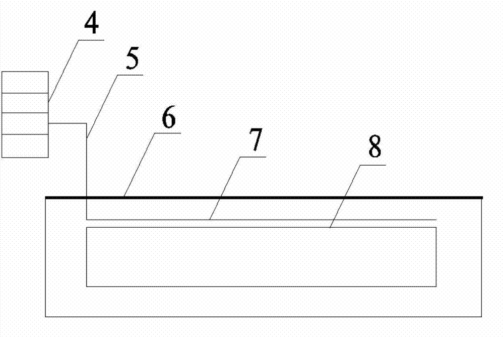
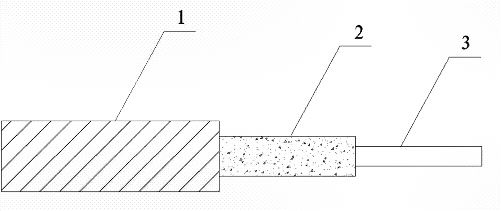
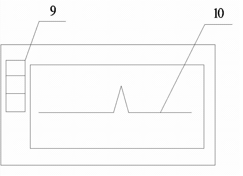
[0027] The on-line monitoring device for pipeline leakage based on optical fiber temperature measurement includes a monitoring host 4, a communication optical cable 5, an armored temperature sensing optical cable 7 and monitoring software; the monitoring host 4 includes a laser source, an optical unit, an optical fiber socket, a signal receiver, a wave Demultiplexer, amplifier, coupler, and processor are placed in the main control room; the armored temperature-sensing optical cable 7 includes double-layer twisted wire armor 1, protective sheath 2, temperature-sensing optical fiber 3, and communication optical cable 5 It is connected with the monitoring host 4 to form an overall hardware monitoring system.

[0028] On-line pipeline leakage monitoring device based on optical fiber temperature measurement, several parts of the hardware monitoring system involved and their functional descriptions:

[0029] 1. Double-layer twisted wire armored temperature-sensing optical cable

[...

Embodiment 2

[0038] An online monitoring method for pipeline leakage based on optical fiber temperature measurement, the specific steps of implementation are as follows:

[0039] 1) laying optical cable

[0040] When the pipeline is laid, the temperature-sensing optical cable is laid out synchronously, and the armored temperature-sensing optical cable 7 and the transmission pipeline 8 are bound together by stainless steel tape. The distance between the optical cable and the pipeline should be less than 30 cm, which can ensure the accuracy of temperature measurement. . During the laying process, if the site conditions do not allow the laying of the entire optical cable, it can also be laid in sections, and then the sections are connected by fusion fibers, and the joints are sealed and protected.

[0041] 2) Signal test

[0042] After the laying is completed, a signal test is performed on the armored temperature-sensing optical cable 7 to confirm that the entire optical cable can carry out...


PUM


Abstract

The invention relates to a pipeline leakage on-line monitoring device and method based on f fiber temperature detection, and belongs to the technical field of pipeline monitoring. The fiber temperature detection based pipeline leakage on-line monitoring device is characterized in that a monitoring main machine is communicated with a temperature sensing optical cable in a communication optical cable way or a wireless signal transmission way; and a light signal sent from the laser source of the monitoring main machine is transmitted to a microprocessor through the temperature sensing optical cable, a signal receiver, a wavelength division multiplexer and an amplifier for processing. The fiber temperature detection based pipeline leakage on-line monitoring method comprises the following steps that: the monitoring main machine is communicated with the temperature sensing optical cable in the communication optical cable way or the wireless signal transmission way; the temperature sensing optical cable senses the change of pipeline leakage temperature and generates a reflected light sensing signal for a laser of the laser source; the signal receiver receivers the light signal and transmits to the microprocessor through the wavelength division multiplexer and the amplifier for processing; and the microprocessor analyzes and displays on-line monitored pipeline leakage. The pipeline leakage on-line monitoring device and method based on the fiber temperature detection have the advantages of wide coverage range, high positioning accuracy, short response time, low false alarm rate, real-time on-line detection, and the like.

Description

technical field [0001] The invention belongs to the technical field of pipeline monitoring, in particular to an online pipeline leakage monitoring device and method based on optical fiber temperature measurement. Background technique [0002] At present, pipeline transportation is the most important energy and chemical raw material in modern society - the main transportation mode of petroleum. Due to its low transportation cost and wide coverage, it is widely used. However, due to internal and external corrosion of pipelines, environmental foundation decline, accidental excavation and other reasons, oil pipeline leakage incidents occur from time to time, which not only cause serious economic losses, but also cause great harm to the environment. [0003] There are three main methods for the existing leakage monitoring of oil pipelines. One is to monitor the leakage through the negative pressure wave generated by the internal and external pressure difference when the pipeline ...

Claims


Application Information

Patent Timeline
Patent Type & Authority Applications(China)
IPC IPC(8): F17D5/02G01K11/32G01K11/324
Inventor 胡欣
Owner E TECH ENERGY TECH DEV CORP
Learn More