
Detachable guide edge and inner side rerailer

A technology of rerailing device and guide rib, which is applied in transportation and packaging, equipment fixed on the track, railway car body parts, etc. It can solve the problems of short rerailing distance, lack of wheel flange grooves, poor material hardness, etc., and achieve Accurate positioning, firm installation and light weight

Active Publication Date: 2013-01-30
郑州力德瑞思科技有限公司
View PDF7 Cites 6 Cited by
  • Summary
  • Abstract
  • Description
  • Claims
  • Application Information

AI Technical Summary

Problems solved by technology

[0003] The object of the present invention is: aiming at the deficiencies of the prior art, to propose a detachable guide rib and an inner rerailer, which overcomes the inability of the original rerailer and the track to be fixed firmly and the lack of wheel flange grooves to effectively guide the Disadvantages of re-tracking, short re-tracking distance, poor casting material hardness and large angle between guide rib and rail after installation

Method used


Image

  • Detachable guide edge and inner side rerailer
  • Detachable guide edge and inner side rerailer
  • Detachable guide edge and inner side rerailer

Examples


Embodiment 1

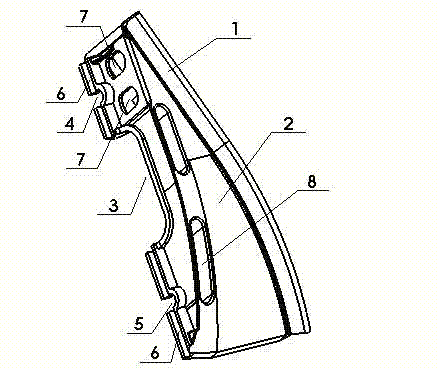
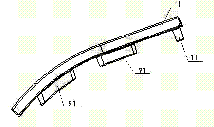
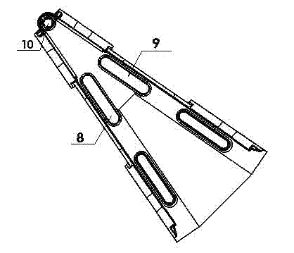
[0027] Embodiment one: if Figure 1 to Figure 5 with Figure 7 As shown, the detachable guide rib and the inner rerailer of the present invention are a detachable guide rib 1, which includes a guide rib body and a fixed protrusion, and the lower surface of the guide rib 1 is a plane and an arc surface or a parabolic surface The composite surface is formed, the plane is tangent to the arc surface or the parabolic surface, and one end of the guide rib 1 has a protrusion 11, and the other end is at least provided with a left guide rib-shaped slot 8 or The right guide rib-shaped slot 9 matches the bar-shaped protrusion 91. The cross-section of the detachable guiding edge 1 is a parabola or a triangle or a rectangle or a trapezoid.

[0028] An inner rerailer includes an inner rerailer body and a detachable guide edge 1. The upper sliding surface 2 of the rerailer is a composite surface composed of a plane and an arc surface, the plane and the arc surface are tangent, and the plan...

Embodiment 2

[0029] Embodiment 2: The structure of Embodiment 2 is basically the same as that of Embodiment 1, and will not be repeated. The inner rerailer is a little different in that the upper sliding surface 201 of the inner rerailer is an arc surface with a radius of 1200-2000 mm, and the lower surface of the detachable guide rib 101 is in line with the upper sliding surface 201 of the inner rerailer. Matching arc faces.


PUM


Abstract

The invention relates to auxiliary railway equipment and discloses a detachable guide edge and inner side rerailer, which overcomes the defects that the original rerailer cannot be firmly fixed to rails, cannot effectively guid the rerailing due to absence of a rim slot and has a short rerailing distance, and an included angle between a guide edge and the steel rail after installation is large. According to the detachable guide edge and inner side rerailer, the upper sliding surface of the inner side rerailer is a curved surface, and the side face of the inner side rerailer is provided with a reinforcing frame; crossed gridded reinforcing ribs are arranged in the frame in a staggered mode; an arched notch which corresponds to a sleeper is arranged in the middle of the bottom surface of the rerailer, the side face of the bottom surface of the rerailer is provided with a clamping groove, and the two ends of the bottom surface of the rerailer are provided with insertion slots, jacks and mounting hole grooves matched with configuration bolts; the guide edge and the inner side rerailer are detachably arranged; the cross section of the guide edge is in the shape of a paraboloid or a triangle or a rectangle or a trapezoid; and an included angle between the guide edge and the steel rail ranges from 15 to 25 degrees. The detachable guide edge and inner side rerailer can meet the requirements on rescue under different road conditions and is firm to mount, easy to guide, light in weight and convenient to mount and transport.

Description

technical field [0001] The invention relates to railway auxiliary equipment, in particular to a detachable guide rib and inner rerailer. Background technique [0002] At present, with the rapid development of my country's railway transportation, derailment of railway locomotives also occurs occasionally. Once derailment occurs, it may cause serious loss of personnel and property, so rerailers also appear in large numbers. Existing rerailers can be divided into herringbone rerailers, sea cucumber type rerailers, two-way rerailers and single-piece rerailers from the structure, but they all have some problems, such as not universal, large guide angle , The installation is too high and the hardness of the material is poor. Chinese patent ZL200920092182.4 discloses "A Rerailing Device". The rerailing device relies on iron chains to fix the rails, and the force is not stable when rerailing, and it is easy to collide with parts at the bottom of the locomotive when it is installed ...

Claims


Application Information

Patent Timeline
Patent Type & Authority Applications(China)
IPC IPC(8): B61K5/06
Inventor 崔德志杨忠阳陈新建刘建新刘作祥唐威
Owner 郑州力德瑞思科技有限公司
Learn More