
Current reference circuit

A technology of current reference and reference current, which is applied in the direction of adjusting electrical variables, control/regulation systems, instruments, etc., can solve the problems of current copy accuracy drop and achieve high-precision results

Active Publication Date: 2013-01-23
GUANGZHOU RUNXIN INFORMATION TECH
View PDF5 Cites 17 Cited by
  • Summary
  • Abstract
  • Description
  • Claims
  • Application Information

AI Technical Summary

Problems solved by technology

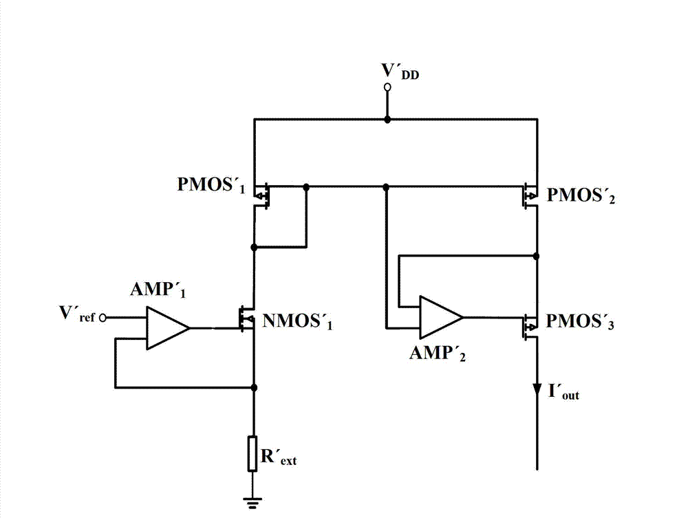
It can be seen that NMOS' 1 The overdrive voltage is the supply voltage V' DD with reference voltage V' ref The difference is limited, so the maximum current value in the reference current range is limited, and the limit for the minimum current value in the reference current range is: when the reference current is small, PMOS' 1 and PMOS' 2 It will enter the sub-threshold, and the influence of leakage will lead to a decrease in the accuracy of current copying

Method used


Image

  • Current reference circuit
  • Current reference circuit
  • Current reference circuit

Examples


Embodiment Construction

[0015] Below, in conjunction with accompanying drawing and specific embodiment, the present invention is described further:

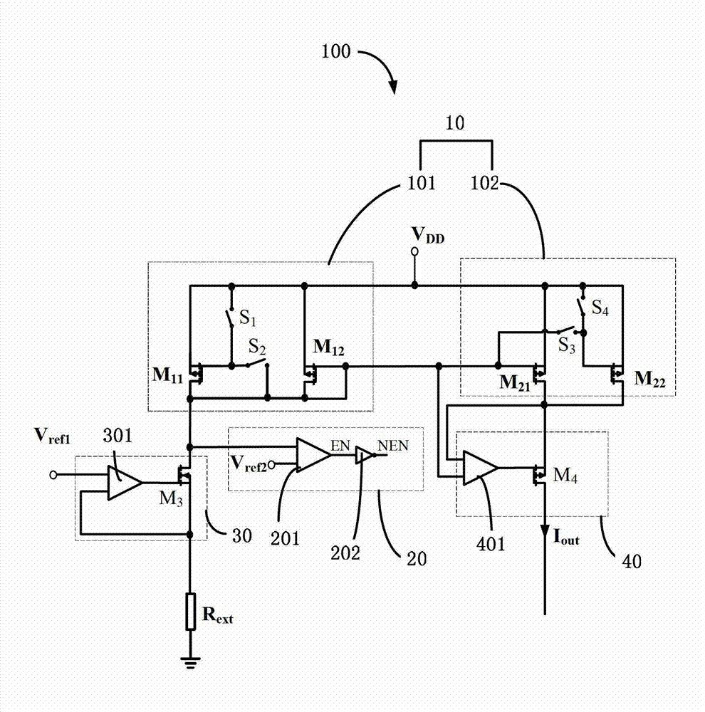
[0016] Such as figure 2 Shown is the circuit diagram of the current reference circuit of the present invention. relatively figure 1 In terms of, the current reference circuit 100 of the present invention will figure 1 PMOS' in 1 The tube is replaced by two or more MOS tubes connected by multiple controllable switches S, PMOS' 2 The tube is replaced by two or more MOS tubes connected through multiple controllable switches S, so as to control the turn-on and disconnection of the controllable switch S according to the size of the generated reference current, thereby controlling the width-to-length ratio of the MOS tubes on both sides of the current mirror size. When the reference current is too small, the width-to-length ratio of the MOS tubes on both sides of the current mirror is controlled by the controllable switch S to ensure that the MOS tubes ...


PUM


Abstract

The invention discloses a current reference circuit which comprises at least two first MOS (Metal Oxide Semiconductor) tubes, second MOS tubes, controllable switches and a voltage comparison circuit, wherein the number of the second MOS tubes is the same as that of the first MOS tubes, the number of the controllable switches is the same as the sum of the number of the first MOS tubes and the number of the second MOS tubes. A reference voltage Vref1 provided by a reference voltage source is loaded on an adjustable resistor to produce a reference current, and the first MOS tubes and the second MOS tubes form a current mirror by the controllable switches. The voltage comparison circuit is used for controlling the breakover and the break of all the controllable switches, so that the structure of the current mirror can be controlled, and the width-to-length ratio of the MOS tubes on the two sides of the current mirror can be adjusted. The current reference circuit disclosed by the invention can provide large-scale reference current, and meanwhile, ensure that the provided reference current has high precision.

Description

technical field [0001] The invention relates to the field of integrated circuits, in particular to a current reference circuit. Background technique [0002] In integrated circuits, current reference circuits are widely used. With the continuous improvement of the performance requirements of the chip in the peripheral application environment, the requirements for the range and accuracy of the current provided by the current reference circuit are also getting higher and higher. The existing common method of providing high-precision and wide-range reference current is to design a high-precision voltage reference circuit in the chip to generate a reference voltage independent of power supply voltage, temperature and process, and then add this reference voltage to the off-chip On the resistor, various current values ​​can be obtained by changing the size of the off-chip resistor. Such as figure 1 Shown is the circuit diagram of a typical current reference circuit. V' ref is...

Claims


Application Information

Patent Timeline
Patent Type & Authority Applications(China)
IPC IPC(8): G05F1/56
Inventor 万为曾明辉毛锴
Owner GUANGZHOU RUNXIN INFORMATION TECH
Learn More