
Apparatus and method for measuring the weight of a continuous flow of reticulated fibrous material

A technology of fiber materials and mesh fibers, which is applied in the field of non-woven net devices, can solve the problems of not providing correction factors, etc.

Active Publication Date: 2016-02-24
TRUTZSCHLER NONWOVENS
View PDF13 Cites 0 Cited by
  • Summary
  • Abstract
  • Description
  • Claims
  • Application Information

AI Technical Summary

Problems solved by technology

In fact the document, although referring in a general way to correcting the weight per unit area during the formation of the web upstream of the crosslapper, does not give any specific indication on how this is achieved and how the correction factor is obtained

Method used


Image

  • Apparatus and method for measuring the weight of a continuous flow of reticulated fibrous material
  • Apparatus and method for measuring the weight of a continuous flow of reticulated fibrous material

Examples


Embodiment Construction

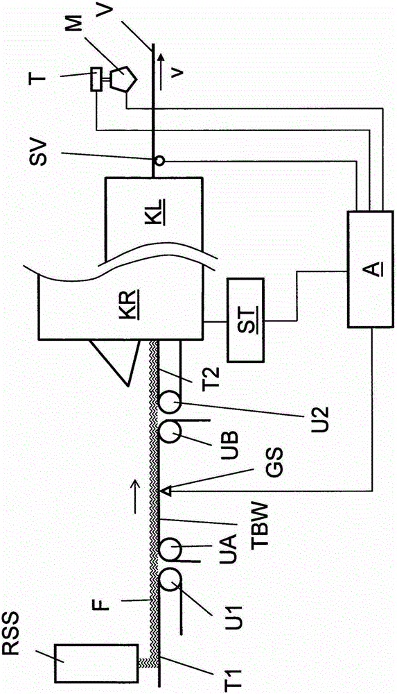
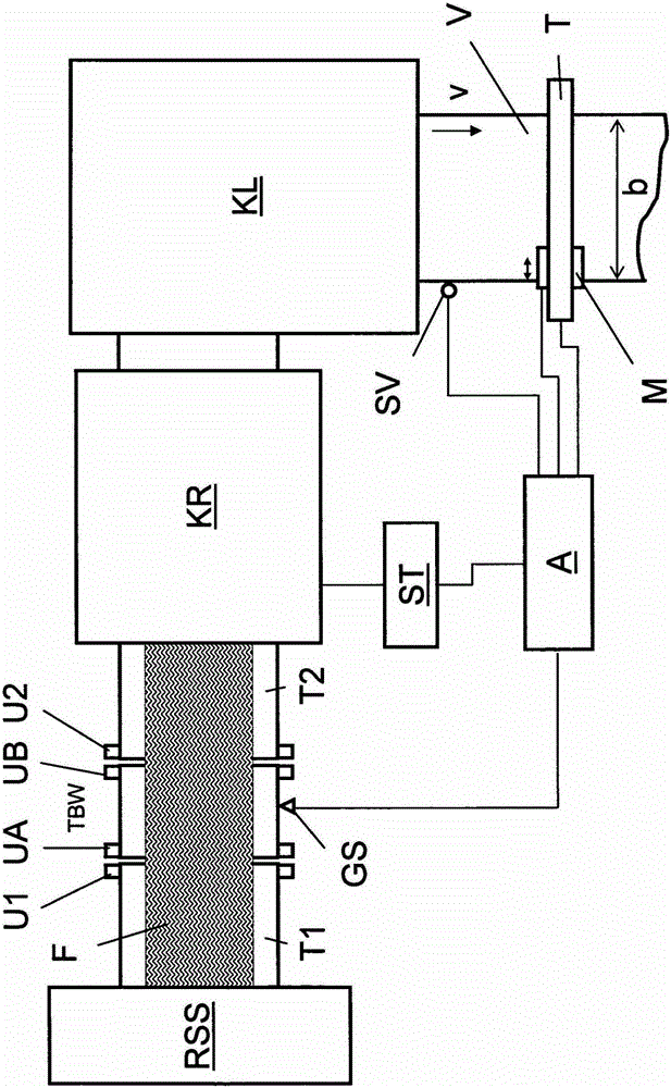
[0034] A vibration cute feed RSS forms a reticular fiber layer F on the first conveyor T1. The first conveyor belt T1 is guided around guide rollers U1 and in this region conveys the fiber layer F to a third endless conveyor belt TBW which circulates under tension in the direction of the arrows around guide rollers UA, UB. A further guide roller U2 extends parallel to the guide roller UB, which tensions the other conveyor belt T2. In the region of the guide rollers UB, U2, the fiber layer F is conveyed from the third endless conveyor belt TBW to the other conveyor belt T2. The conveyor belt T2 is coupled to a card KR (indicated only schematically in the drawing) and feeds this card.

[0035]Immediately downstream of the card KR is a crosslapper KL (also indicated only schematically) which superimposes the fluff formed by carding in order to obtain a nonwoven V. At the outlet of the crosslapper KL the nonwoven V has a speed v which is determined by a speed sensor SV. The spe...


PUM


Abstract

The invention relates to a method and device for measuring the weight of an endless flow of web-shaped fiber material, which is conveyed on a circulating conveyor belt, wherein a signal corresponding to the weight of the fiber material on the conveyor belt is generated by means of an associated measuring system and said signal is used in particular to control a machine that processes the fiber material. According to the invention, a signal corresponding to the mass per unit area and the weight per unit area of the material is determined downstream of the measuring system (GS, TBW) of the conveyor belt (TBW) in the conveying direction. The signal is considered in the evaluation of the weight signal detected in the area of the circulating conveyor belt (TBW). In addition, a signal of a measuring device (M) for determining the mass per unit area and the weight per unit area of the fiber material (F, V) is fed to an evaluating device (A), wherein the measuring device (M) is arranged downstream of the conveyor belt (TBW) in the conveying direction.

Description

technical field [0001] The present invention relates to apparatus and methods for processing a continuous flow of reticulated fibrous material into a nonwoven web. Background technique [0002] A device for transferring a fiber layer to a card is known from DE 10 2007 014 694 A1. The transfer path starts at a changing chute feeder which deposits the fibers on the first conveyor belt. Via other driven conveyor belts, the fiber layer reaches an endless conveyor belt with weighers and from there to the inlet of the carding machine. In a belt scale, measuring devices and sensors arranged there are used to detect a signal corresponding to the weight of the fiber layer on the belt of the belt scale. This signal is supplied to a control device which processes the supplied signal in relation to the speed signal of the card so that the card forms a constantly uniform unwoven fiber. [0003] The fiber layer whose weight is analyzed by the belt scale is transferred from the upstream...

Claims


Application Information

Patent Timeline
IPC IPC(8): D01G21/00D01G23/04D01G23/06D01G31/00D04H1/70
CPCD01G23/04D01G21/00D01G23/06D01G31/006
Inventor 赖因霍尔德·多林伯恩哈德·吕贝纳克
Owner TRUTZSCHLER NONWOVENS
Learn More