
Beam operating handle structure of vertical lathe

A technology for operating handles and vertical lathes, which is applied in the direction of control components, mechanical control devices, feeding devices, etc., which can solve the problems of difficult replacement and maintenance of handle seats, and achieve the effects of improving replacement and maintenance efficiency and simplifying operating procedures

Inactive Publication Date: 2014-08-13
WUXI JINGHUA HEAVY IND EQUIP MFG
View PDF10 Cites 0 Cited by
  • Summary
  • Abstract
  • Description
  • Claims
  • Application Information

AI Technical Summary

Problems solved by technology

[0003] The purpose of the present invention is to overcome the deficiencies in the prior art, and provide a simple, ingenious and reasonable structure of the vertical lathe beam operating handle structure, which effectively solves the problem of Solved the problem of difficult replacement and maintenance of the handle seat

Method used


Image

  • Beam operating handle structure of vertical lathe

Examples


Embodiment Construction

[0009] The present invention will be further described below in conjunction with specific drawings and embodiments.

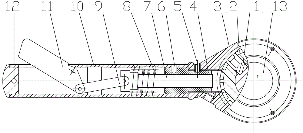
[0010] Such as figure 1 As shown, the crossbeam operating handle structure of a vertical lathe mainly includes a ratchet 2, a handle seat 3, a connecting rod 4, a set screw 5, a set screw 6, a rod 7, a spring 8, a connecting rod 9, and a sleeve 10 , pinch block 11 and handle 12.

[0011] In the present invention, a pinch block 11 is connected to one end of the connecting rod 9, and the other end of the connecting rod 9 is connected to one end of the rod 7. The rod 7, the connecting rod 9 and the pinch block 11 are assembled into a connecting rod structure, and the connecting rod structure is installed In the sleeve 10, the other end of the rod 7 is inserted into the groove of the ratchet 2, the connecting rod 4 is transitionally fitted with the sleeve 10, the connecting rod 4 is threaded with the handle seat 3, and the connecting rod 4 is connected with the ha...


PUM


Abstract

The invention relates to a beam operating handle structure of a vertical lathe. The beam operating handle structure of the vertical lathe comprises a pinching block, a sleeve, a connecting rod, a rod, a handle seat, a ratchet, a screw and a connection rod. The pinching block is connected with one end of the connecting rod, the other end of the connecting rod is connected with one end of the rod, the connection rod and the pinching block are mounted to a connecting rod structure, the connecting rod structure is mounted in the sleeve, other end of the rod is inserted in a groove of the ratchet, the ratchet is connected with the screw through a flat key, the connection rod and the sleeve are in transition fit with each other, and the connection rod is in threaded connection with the handle seat. A spring is mounted on the rod. The connection rod is added between the handle seat and the sleeve, and the connection rod is in threaded connection with the handle seat, so that the handle seat only needs to be replaced by returning a fastening screw to screw down the connection rod when the handle seat breaks. Firmness of the handle structure is increased greatly, replacement and maintenance efficiency is high, and operating process is simplified.

Description

technical field [0001] The invention belongs to the field of vertical lathes, in particular to a crossbeam operating handle structure of a vertical lathe. Background technique [0002] In the vertical lathe, the beam operating handle structure plays an important role as the basic operating structure. Through the operation of the handle mechanism, the tool holder can move in the horizontal and vertical directions, ensuring that the tool holder remains in the power-off state. It can be moved manually, which eliminates the situation that the tool holder cannot move under unexpected conditions. In the prior art, the handle structure of the crossbeam operating handle of the vertical lathe is usually designed in such a way that the handle seat and the casing are cast as one. Since the material of the handle seat is hard and brittle cast iron, when it is broken by a large impact force, the It needs to disassemble the feed box and the screw rod for replacement and maintenance, whic...

Claims


Application Information

Patent Timeline
Patent Type & Authority Patents(China)
IPC IPC(8): G05G1/10B23Q5/22
Inventor 朱振强
Owner WUXI JINGHUA HEAVY IND EQUIP MFG
Learn More