Method for catching and positioning electric arc of electrified railway contact net

A technology of electrified railway and positioning method, which is applied in the direction of measuring electricity, measuring electrical variables, optical testing flaws/defects, etc., and can solve problems such as inability to complete catenary continuous testing

Inactive Publication Date: 2013-01-16
唐粮
View PDF1 Cites 20 Cited by
  • Summary
  • Abstract
  • Description
  • Claims
  • Application Information

AI Technical Summary

Problems solved by technology

The disadvantage of this method is that it is still a single-point detection method, which can only monitor the temperature of the position where the sensor is installed, and cannot complete the continuous detection of the entire line of the catenary.

Method used


Image

  • Method for catching and positioning electric arc of electrified railway contact net
  • Method for catching and positioning electric arc of electrified railway contact net
  • Method for catching and positioning electric arc of electrified railway contact net

Examples


Embodiment 1

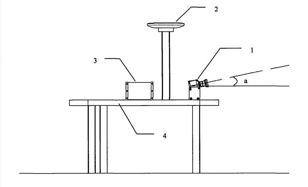
[0042] Embodiment 1: Assuming that the running speed of the electric locomotive is 350 km / h, i.e. 97.2 m / s, the frequency of the GPS receiver is 2 Hz, the frequency of the IMU is 256 Hz, and the positioning accuracy of the differential GPS / IMU is centimeter level, in this embodiment The high-speed digital imaging device 1 selects a high-speed digital camera, and the shooting speed is 2000 frames per second, so the positioning accuracy of the arc is about 5 cm. If you need to improve the positioning accuracy, you can choose a higher shooting speed. The capture and positioning of the arc does not require high image resolution, and the optimization of storage and arc recognizability must be considered comprehensively here. The lens of the high-speed digital imaging device 1 should be a fixed-focus lens, and the focal point is the contact point between the pantograph and the railway catenary.

Embodiment 2

[0043] Embodiment 2: in the present embodiment, high-speed digital imaging equipment 1 selects high-speed digital thermal infrared camera for use, and the shooting speed is 160 frames per second. Assuming that the running speed of the electric locomotive is 300 kilometers per hour, that is, 83.3 meters per second, the GPS receiver The frequency is 2Hz, the frequency of the IMU is 256Hz, and the positioning accuracy of the differential GPS / IMU is centimeter level. The acquired data will be continuous temperature data every 0.5 meters. During data processing, the temperature range can be set to classify the data , this method can not only locate the start and end positions of the arc, but also monitor the abnormal temperature of the entire line of the catenary. Similarly, the way to improve positioning accuracy is to choose a thermal infrared camera with faster shooting speed.


PUM


Abstract

The invention relates to the field of monitoring and safety of electrified railways, in particular to a method for catching and positioning an electric arc of an electrified railway contact net based on a high-precision global positioning system (GPS) / inertia measurement unit (IMU) positioning and orientation technology and a high-speed digital imaging technology. When a high-speed camera or a high-speed digital camera of high-speed digital imaging equipment 1 performs shooting or exposure, a pulse event signal is returned to an industrial control computer 5; the current GPS time is recorded, so that an exposure time file is formed; the high-speed digital imaging equipment 1, a GPS receiver 2 and an IMU 3 use the same GPS time, so that digital frame images of the electric arc are automatically extracted from an image sequence after data are processed to generate a moving trace of a power locomotive; and the exposure times of the electric arc images are matched with the moving trace of the power locomotive, so that a start position, an end position, a delay time period, a lasting distance and a temperature distribution situation of the electric arc can be accurately determined.

Description

[0001] This application is a divisional application [0002] Original application number: 201010263424.9 [0003] Original filing date: August 26, 2010 [0004] Original title of the invention: A system and method for arc capture and positioning of electrified railway catenary technical field [0005] The invention relates to the field of electrified railway monitoring and safety, in particular to a catenary arc capture and positioning system and method for electrified railways based on high-precision global positioning system GPS / inertial measurement unit IMU positioning and orientation technology and high-speed digital imaging technology. Background technique [0006] In the electrified railway, the catenary is the main power supply equipment of the electrified railway, and the electric locomotive obtains electric energy through the catenary. Current receiving refers to the dynamic process of the contact between the bow head of the pantograph of the high-speed train and ...

Claims


Application Information

Patent Timeline
IPC IPC(8): G01R31/00G01N21/88
Inventor 唐粮
Owner 唐粮
Why Eureka
Try Eureka