Method and system used in turbocharged engine

A technology of engines and compressors, applied to engine components, combustion engines, engine control, etc., can solve problems such as delays

Inactive Publication Date: 2013-01-16
FORD GLOBAL TECH LLC
View PDF6 Cites 10 Cited by
  • Summary
  • Abstract
  • Description
  • Claims
  • Application Information

AI Technical Summary

Problems solved by technology

Furthermore, since LP-EGR and HP-EGR require different control methods, there may be a delay when controlling both LP-EGR and HP-EGR in a short time (transient)

Method used


Image

  • Method and system used in turbocharged engine
  • Method and system used in turbocharged engine
  • Method and system used in turbocharged engine

Examples


Embodiment Construction

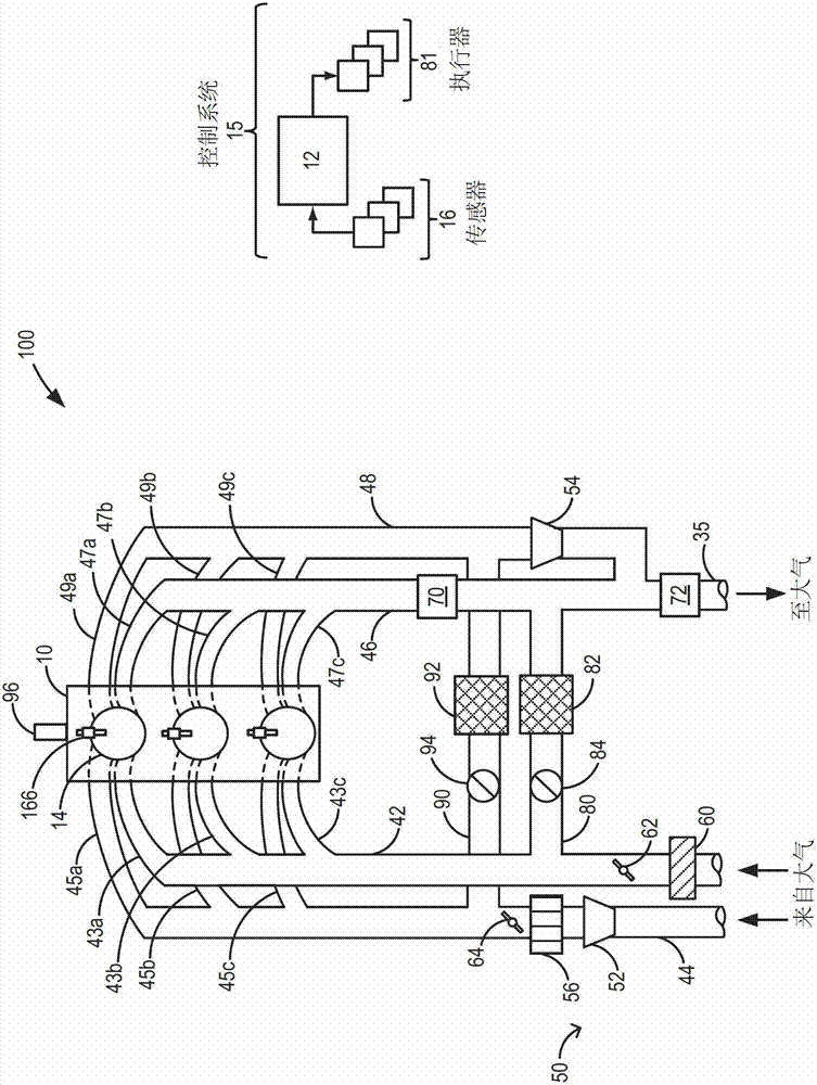
[0028] The following description refers to the Figure 1-3 A system and method for providing air charges of different pressures and / or different compositions (eg, different proportions of fresh air and EGR) to engine cylinders through different intake ports at different times in an engine cycle. Specifically, intake charge at or below BP and intake charge at compressor pressure may be provided to the cylinders separately. Similarly, an intake charge including recirculated exhaust gas and an intake charge including fresh air may be provided to the cylinders separately. Such as Figure 6 In the description, other combinations are possible. The engine controller can be configured to execute control programs such as Figure 4 procedure in ) to open the intake valve of the first cylinder at an earlier timing than the intake valve of the second cylinder ( Figure 5 ) such that the intake charge of the first composition is provided at a different time in the engine cycle than the...


PUM


Abstract

The invention provides a method and a system used in a turbocharged engine. The turbocharged engine comprises a separated air intake system connected with a separated exhaust system. Air inflations of different components, pressures and temperatures can be transmitted to the engine at different circulation points of the engine via the separated air intake system, so that the boost and EGR benefits can be expanded.

Description

【Technical field】 [0001] The present invention relates to a method for improving the thermal efficiency of a turbocharged engine. The method is particularly useful for providing exhaust gas recirculation (EGR) in turbocharged engines. 【Background technique】 [0002] In an effort to meet stringent federal government emission standards, engine systems may be equipped with EGR systems in which at least a portion of exhaust gas is recirculated to the engine intake. Especially at higher levels of engine boost, this type of EGR system can reduce exhaust emissions while also improving fuel economy. [0003] One example of this type of EGR system is described in US Patent 6,135,088. Therein, the first intake port of the engine cylinder is configured to deliver EGR and the second intake port is configured to deliver fresh air boosted by the compressor to the cylinder. In this way, low pressure EGR can be delivered to the cylinders. [0004] However, applicants are aware that such...

Claims


Application Information

Patent Timeline
IPC IPC(8): F02D23/00F02D13/02F02D43/00
CPCF02B33/44F02D43/00F02D2041/001Y02T10/144F02M25/0707Y02T10/18F02D2200/0408F02M25/0732F02B33/446F02M25/0744F02B37/02F02D13/0261F02D41/0007Y02T10/47F02D13/02F02D21/08F01N13/107F02D23/00F02D13/0207F02D13/0257F02M25/0709F02D2200/0402F02D41/0065F02M35/10163F02D2200/0416F02D2041/007F02M35/1085F02D13/0238F02M26/05F02M26/06F02M26/24F02M26/38Y02T10/12Y02T10/40
Inventor R·D·皮尔西弗J·N·阿勒瑞
Owner FORD GLOBAL TECH LLC
Why Eureka
Try Eureka