
Prefabricated cast-in-place shear wall structure

A shear wall and cast-in-place technology, which is applied to walls, building components, building structures, etc., can solve problems such as difficulty in meeting living requirements, achieve good safety, and reduce the amount of high-altitude operations

Inactive Publication Date: 2013-01-16
沈阳市东陵区(浑南新区)卓科技术开发中心
View PDF0 Cites 2 Cited by
  • Summary
  • Abstract
  • Description
  • Claims
  • Application Information

AI Technical Summary

Problems solved by technology

[0002] With the development of the economy, traditional housing construction methods are difficult to meet people's rapidly increasing living requirements

Method used


Image

  • Prefabricated cast-in-place shear wall structure
  • Prefabricated cast-in-place shear wall structure
  • Prefabricated cast-in-place shear wall structure

Examples


Embodiment 1

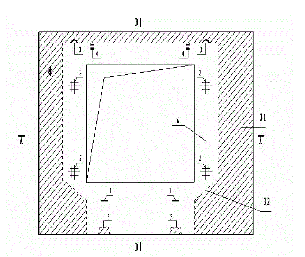
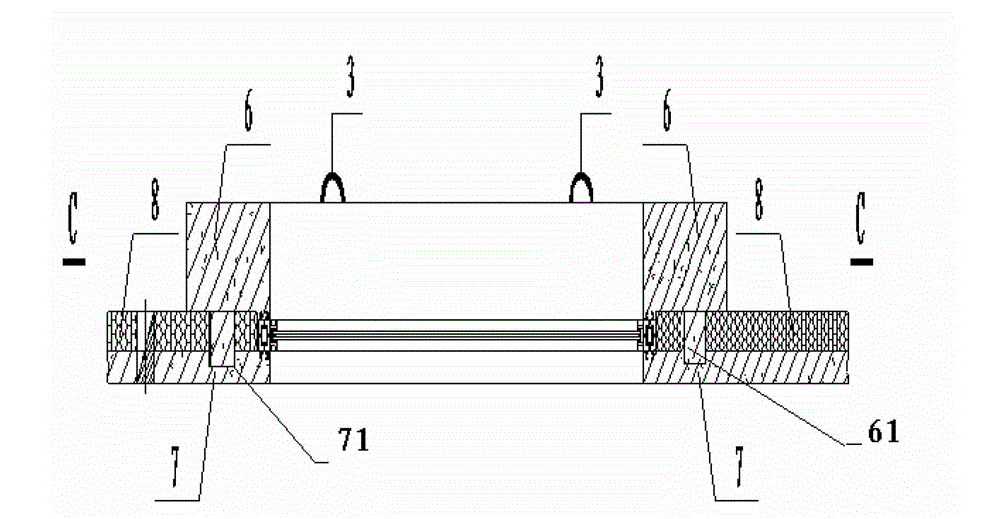
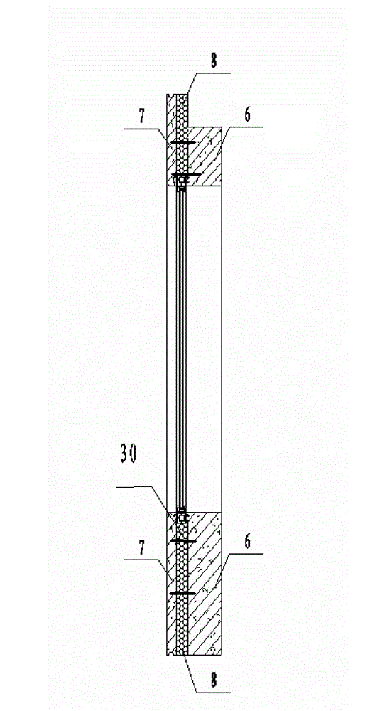
[0041] Such as Figure 1 to Figure 6 Shown is a shear wall structure with a window, including an outer wall 7, an insulating material layer 8, and an inner wall 6, and the insulating material layer 8 is interposed between the outer wall 7 and the inner wall 6 In between, the inner wall 6 is provided with a convex portion 61, and the outer wall 7 is provided with a concave portion 71, and the steel bars exposed by the convex portion 61 and the concave portion 71 are poured with cement so that the outer wall and the inner wall are fixed. become one.

[0042] The other parts between the inner wall 6 and the outer wall 7 are connected by tie bars 30. The inner wall 6 is composed of two parts, one part is a prefabricated part, and the other part is a cast-in-place part 31. The inner wall is prefabricated Some are located in the middle of the outer wall 7, and the area of ​​the prefabricated part of the inner wall is smaller than that of the outer wall 7 to leave space for the cast...

Embodiment 2

[0049] Figure 7 ~ Figure 10 It is another embodiment of the present invention. The difference between this embodiment and Embodiment 1 is that the shear wall does not have reserved holes (windows), but is integral, the same as Embodiment 1, including the outer wall 7, thermal insulation Material layer 8, inner page wall 6, the thermal insulation material layer 8 is interposed between the outer page wall 7 and the inner page wall 6, the inner page wall 6 and the outer page wall 7 are connected by tie bars 30, the The inner wall 6 is made up of two parts, one is a prefabricated part, and the other is a cast-in-place part 31. The prefabricated part of the inner wall is located in the middle of the outer wall 7, and the area of ​​the prefabricated part of the inner wall is smaller than the The outer page wall 7 is to reserve the space of the cast-in-place part, and the inner page wall is also provided with a lifting point 3, a steel bar handle 1, and a position adjustment device;...


PUM


Abstract

The invention discloses a prefabricated cast-in-place shear wall structure, which is characterized by comprising outer page walls, heat preservation material layers and inner page walls, wherein the heat preservation material layers are arranged between the outer page walls and the inner page walls; protruded parts are arranged on the inner page walls; sunken parts are arranged on the outer page walls; exposed steel bars are retained on the protruded parts and the sunken parts; the outer page walls and the inner page walls are fixedly combined to form a whole through cement pouring; no direct contact part is formed between the outer page walls and the inner page walls; and pull bars for connecting the outer page walls and the inner page walls are arranged. The prefabricated cast-in-place shear wall structure has the following advantages: 1, the construction quality is improved; 2, energy saving and environment friendliness are achieved; 3, the working period is shortened, and industrial production is realized; and 4, the construction safety is improved.

Description

technical field [0001] The invention relates to the field of building materials, in particular to a prefabricated cast-in-place shear wall structure. Background technique [0002] With the development of the economy, the traditional housing construction methods are difficult to meet people's rapidly increasing living requirements. Therefore, how to quickly realize housing production has become an objective requirement of the society. Taking this as an opportunity, countries such as Europe, America and Japan have reformed the traditional construction methods and introduced production methods in the manufacturing field. Housing production has gradually realized industrialization, and various countries have formed It has established its own mature industrialized housing system. [0003] Industrialized housing is currently the main mode of production in developed countries such as the United States and Japan. With the rapid development of China's economy and to meet the needs o...

Claims


Application Information

Patent Timeline
IPC IPC(8): E04B2/86E04B1/76
Inventor 任凯
Owner 沈阳市东陵区(浑南新区)卓科技术开发中心
Learn More