Device and method for polishing symmetrical optical component of small-caliber rotating shaft
A polishing device and optical element technology, applied in grinding/polishing equipment, abrasive feeding device, used abrasive processing device, etc., can solve the problem of large outward expansion, large fluid disturbance, unstable performance, etc. To achieve the effect of enhancing the sliding effect and stability, improving the removal efficiency and reducing the air interference
- Summary
- Abstract
- Description
- Claims
- Application Information
AI Technical Summary
Problems solved by technology
Method used
Image
Examples
Embodiment 1
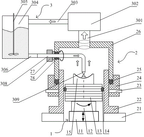
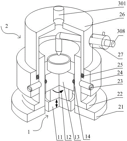
[0039] see figure 1 , the small-diameter rotary axis-symmetrical optical element polishing device includes a sealed container mechanism 2, a worktable drive system 1 installed in the inner cavity of the sealed container mechanism 2, and a polishing fluid circulation system 3 connected to the sealed container mechanism 2;
[0040] The workbench drive system 1 includes a servo lifting platform 11 capable of moving up and down, a servo rotating platform 12 capable of rotating and moving on the servo lifting platform 11, and a servo rotating platform 12 for fixing a workpiece 15 with a symmetrical curved surface on the rotary axis. The workpiece support table 13;
[0041] The sealed container mechanism 2 includes a circular support platform 21, a sealing cylinder 22 arranged on the circular support platform 21, a sealing cylinder 22 sleeved on the upper part of the sealing cylinder 22 and locked and connected with the sealing cylinder 22 through an adjustable positioning block 24...
Embodiment 2
[0045] see Figure 5 , the small-diameter rotary axis-symmetrical optical element polishing device includes a sealed container mechanism 2, a worktable drive system 1 installed in the inner cavity of the sealed container mechanism 2, and a polishing fluid circulation system 3 connected to the sealed container mechanism 2;
[0046] The workbench drive system 1 includes a servo lifting platform 11 capable of moving up and down, a servo rotating platform 12 capable of rotating and moving on the servo lifting platform 11, and a servo rotating platform 12 for fixing a workpiece 15 with a symmetrical curved surface on the rotary axis. The workpiece support table 13;
[0047] The sealed container mechanism 2 includes a circular support platform 21, a sealing cylinder 22 arranged on the circular support platform 21, a sealing cylinder 22 sleeved on the upper part of the sealing cylinder 22 and locked and connected with the sealing cylinder 22 through an adjustable positioning block 24...
Embodiment 3
[0052] The method for polishing a small-diameter rotary axisymmetric optical element based on the device of the present invention comprises the following steps:
[0053] (1) Fix the workpiece 15 with a small-diameter rotary axis-symmetrical curved surface on the workpiece support table 13, and adjust the distance between the curved surface of the rotary axis-symmetrical curved surface workpiece 15 and the flow-limiting nozzle 309 to 4 mm;
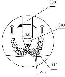
[0054] (2) Add polishing fluid containing fine abrasive particles 311 into the liquid storage tank 304; start the agitator 305 and the suction pump 302 to reduce the pressure in the negative pressure space, so that the polishing fluid passes through the suction pipe 306 and the swing pipe 308 from the The flow-limiting nozzle 309 shoots out and polishes the workpiece 15 with a symmetrical curved surface on the rotary axis, and then returns to the liquid storage tank through the suction pipe 301 and the return pipe 303. The polishing fluid ci...
PUM
 Abstract
Description
Claims
Application Information
 - R&D Engineer
- R&D Manager
- IP Professional
- Industry Leading Data Capabilities
- Powerful AI technology
- Patent DNA Extraction
Browse by: Latest US Patents, China's latest patents, Technical Efficacy Thesaurus, Application Domain, Technology Topic, Popular Technical Reports.
© 2024 PatSnap. All rights reserved.Legal|Privacy policy|Modern Slavery Act Transparency Statement|Sitemap|About US| Contact US: help@patsnap.com


