Self-buckled special chamfering device for stator core

A technology of stator iron core and chamfering device is applied in the direction of manufacturing stator/rotor body, etc., which can solve the problems of high production cost, low efficiency and inconvenient processing.

Active Publication Date: 2013-01-09
ZHEJIANG KAIXUN MECHANICAL & ELECTRICAL
View PDF7 Cites 2 Cited by
  • Summary
  • Abstract
  • Description
  • Claims
  • Application Information

AI Technical Summary

Problems solved by technology

Due to the structure of the self-locking stator core, the punches are interlocked to form a whole. In the prior art, when chamfering the self-locking stator core, it is necessary to press both ends of the self-locking stator core wit...

Method used


Image

  • Self-buckled special chamfering device for stator core
  • Self-buckled special chamfering device for stator core

Examples


Embodiment Construction

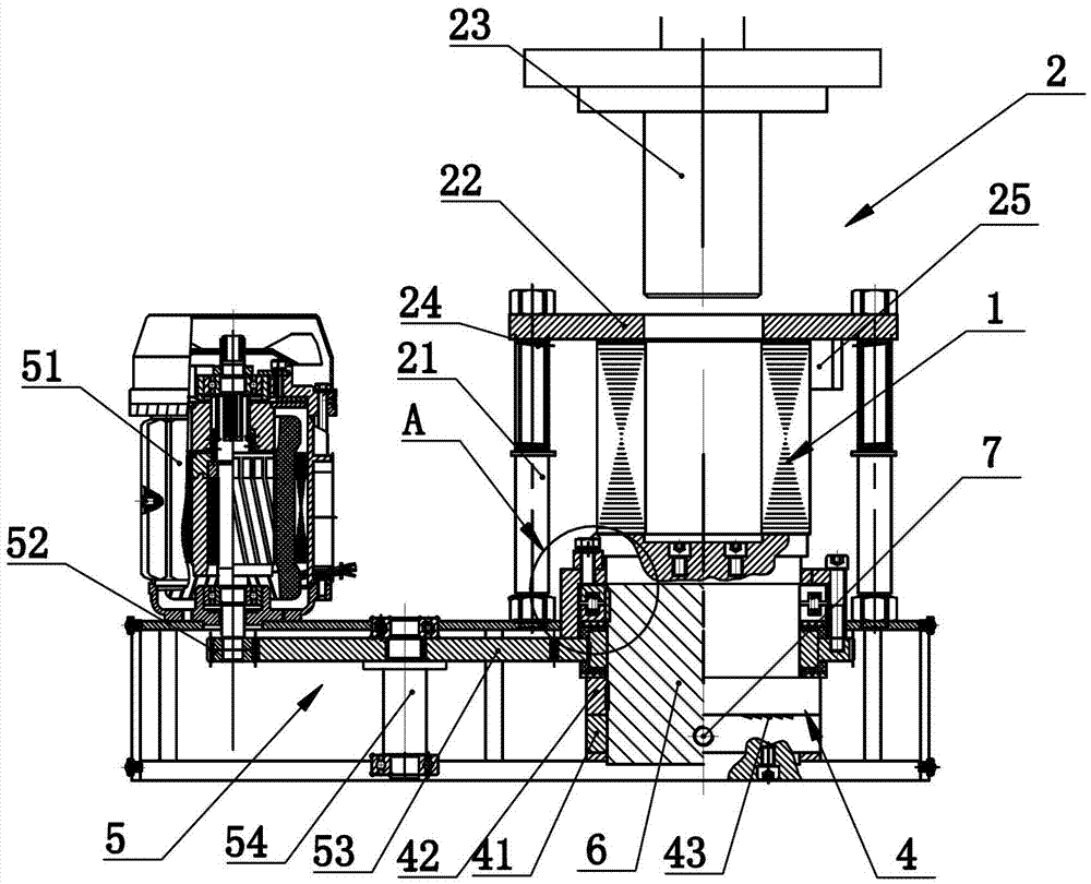
[0017] See attached figure 1 , the special chamfering device for the self-fastening stator core disclosed in the present invention includes a press-fitting mechanism 2 for press-fitting both ends of the stator core 1, a chamfering knife assembly 3, and drives the chamfering knife assembly 3 to approach or move away from the stator iron core. The displacement driving mechanism 4 at the position of one end of the core 1 and the rotation driving mechanism 5 that drives the chamfering knife assembly 3 to rotate around the outer circle of one end of the stator core 1 to chamfer the outer circle of the end of the stator core 1 . By adopting the above technical scheme, when performing the chamfering process on the stator core 1, the stator core 1 is first press-fitted by the press-fit mechanism 2, and then the chamfering knife assembly 3 is driven close to the end of the stator core 1 by the displacement drive mechanism 4 At the outer circle position, finally the chamfering knife ass...


PUM


Abstract

The invention relates to a self-buckled special chamfering device for a stator core, which comprises a pressing mechanism for pressing both ends of the stator core, a chamfering cutter component, a displacement driving mechanism for driving the chamfering cutter component to move close to or away from the excircle position at one end of the stator core, and a rotary driving mechanism for driving the chamfering cutter component to rotate around the excircle at one end of the stator core to chamfer the excircle at the end of the stator core. The technical scheme of the invention has the effects of improving the machining efficiency and lowering the production cost.

Description

technical field [0001] The invention relates to a special chamfering device for a self-fastening stator core. Background technique [0002] There are usually two types of stator cores, namely buckle type and self-fastening type. The buckle-type stator core is formed by buckling the punching pieces through buckle pieces, and the self-fastening stator core is formed by interlocking the punching pieces themselves. Snap together to form a whole. The stator core usually needs to chamfer the outer circles at both ends so that the subsequent assembly process can be carried out more smoothly. Due to the structure of the self-locking stator core, the punches are interlocked to form a whole. In the prior art, when chamfering the self-locking stator core, it is necessary to press both ends of the self-locking stator core with a hydraulic press. In order to improve the stability of the whole, it is then transferred to a lathe to chamfer the outer circles at both ends, which has the di...

Claims


Application Information

Patent Timeline
IPC IPC(8): H02K15/02
Inventor 谢炳亮焦丁崇余立川沈兴君
Owner ZHEJIANG KAIXUN MECHANICAL & ELECTRICAL
Why Eureka
Try Eureka