
Target shape optimization method for aspherical optical element in conventional processing stage

A technology of optical components and traditional processing, applied in optical components, optics, instruments, etc., can solve the problems of excessive surface error of intermediate frequency, excessive removal of workpiece surface, large deviation between spherical surface and aspherical surface, etc.

Inactive Publication Date: 2015-02-18
TSINGHUA UNIV
View PDF0 Cites 0 Cited by
  • Summary
  • Abstract
  • Description
  • Claims
  • Application Information

AI Technical Summary

Problems solved by technology

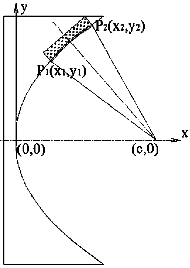
[0016] The purpose of the present invention is to provide a method for optimizing the target shape of an aspheric optical element in the traditional processing stage, so as to solve the problem that the center of the approximate spherical surface is limited to be on the axis of rotation in the traditional solution method, resulting in a relatively large deviation between the obtained approximate spherical surface and the aspheric surface. problem, and can solve the near-spherical surface with the maximum normal deviation as the optimization goal, avoiding the problem of excessive intermediate frequency surface shape error caused by excessive removal of a certain point on the workpiece surface

Method used


Image

  • Target shape optimization method for aspherical optical element in conventional processing stage
  • Target shape optimization method for aspherical optical element in conventional processing stage
  • Target shape optimization method for aspherical optical element in conventional processing stage

Examples


Embodiment Construction

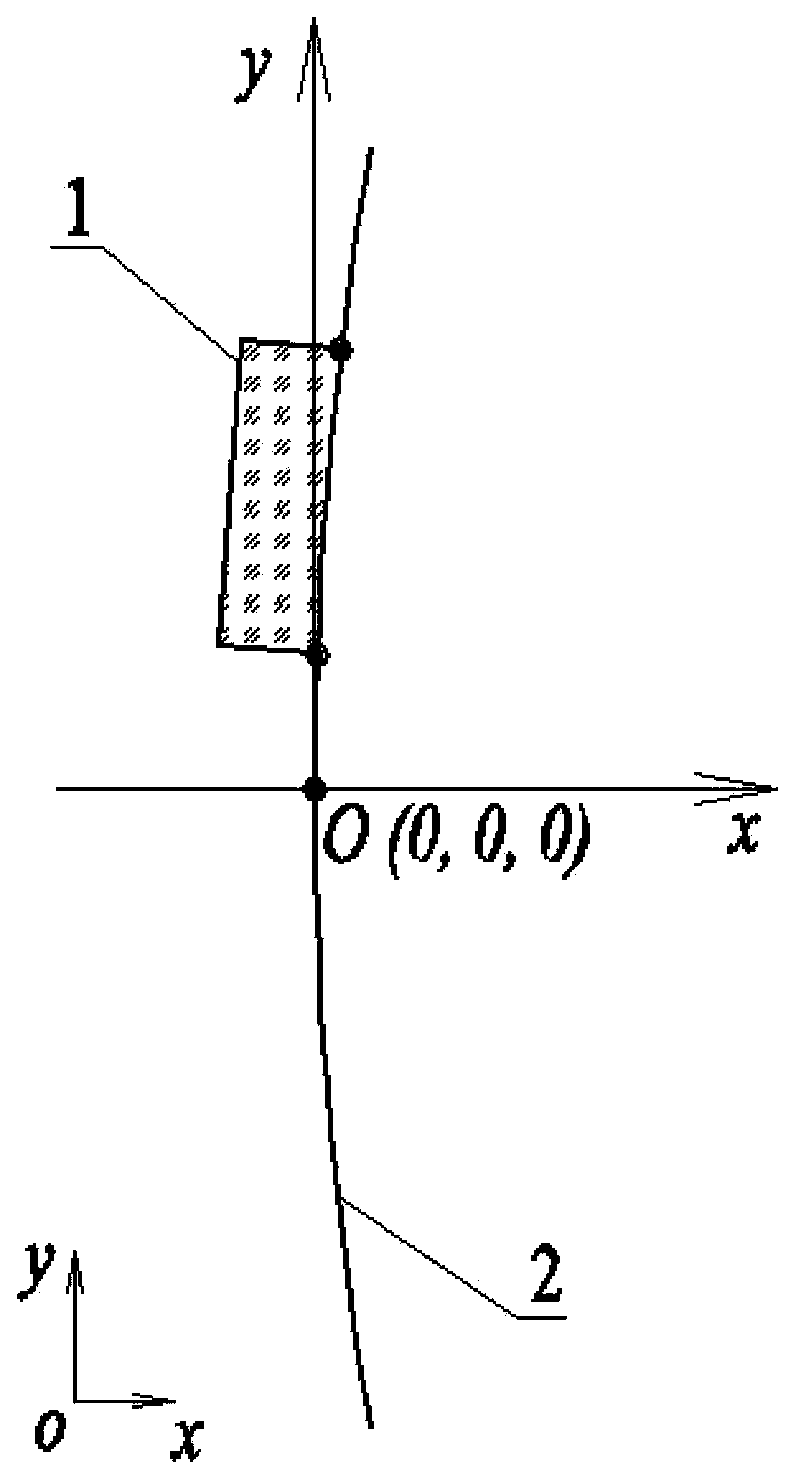
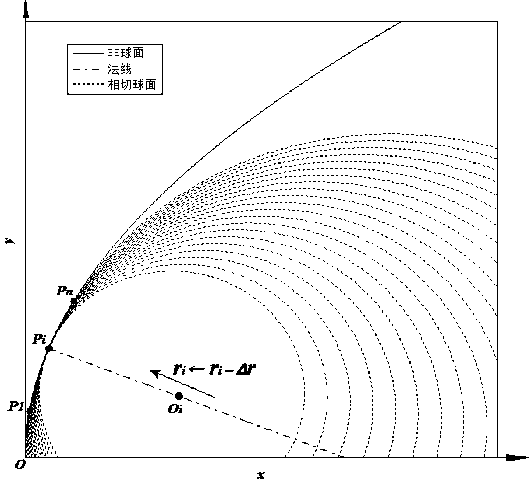
[0059] Such as figure 2 , image 3 As shown, the concave off-axis parabolic mirror 1 is located on the paraboloid of revolution 2 . P 1 P n is the intercept curve obtained by intersecting it with the xoy plane, O i point at P i point on the normal. figure 2 The positional relationship between the concave off-axis paraboloid mirror 1 and the revolution paraboloid 2 is shown as a whole. Concave off-axis parabolic mirror 1 equation is y 2 +z 2 =2400x, y∈[42,143], z∈[-50,50], the unit is millimeter.

[0060] Laser interferometers are usually used to measure the surface shape of workpieces. Since the resolution of the interferometer’s lateral measurement is 0.1 to 0.2 mm, when discretizing the surface equation in the computer, the y direction of two adjacent points in the data point matrix The distances in and z directions are both set to 0.1 mm, so that Δr=0.1 mm.

[0061] The value of n and m determines the level of calculation accuracy, here select n=1000, m=1000×100...


PUM


Abstract

The invention discloses a target shape optimization method for an aspherical optical element in a conventional processing stage, belonging to the technical field of optical processing. A decare right-angle coordinate system is built by taking an optical axis of the aspherical optical element as an x axis and an intersection point of the optical axis and an aspherical surface as an original point; and points on the aspherical optical element are gradually searched by taking a circle center and a radius of a curvature circle of each point on a curve obtained by the intersection of a symmetric plane of the aspherical optical element and the aspherical surface as initial values of a similarly spherical surface, and the position of a spherical center and a radius value of the similarly spherical surface are randomly adjusted, so that the similarly spherical surface can meet a positive removal amount condition. The spherical center of the similarly spherical surface is not limited on a rotating shaft, so that the similarly spherical surface which is better than that obtained by the conventional method can be obtained, and the problem that the manufacturing cost is increased because of over removal of materials is solved; and moreover, the similar spherical surface can be optimized by taking a minimum value of a maximum normal deviation value as a target, so that the similar spherical surface beneficial to reducing processing traces and medium frequency surface shape errors can be obtained.

Description

technical field [0001] The invention belongs to the technical field of optical processing, in particular to a method for optimizing the target shape of an aspheric optical element in a traditional processing stage. Background technique [0002] The surface shape of optical components usually has the following types: plane, spherical, aspheric and free-form surface. Among them, the aspherical surface used in the optical system is usually a curved surface with rotational symmetry such as a paraboloid, a hyperboloid, and an ellipsoid. For convenience, the rotationally symmetric aspheric surface may be simply referred to as aspherical surface. The off-axis aspheric surface is taken from the aspheric surface, but deviates from the rotational axis of the aspheric surface, which is a special kind of aspheric surface. Generally, the off-axis aspheric element itself has no rotational symmetry, but because it is taken from the aspheric surface, the off-axis aspheric surface is also ...

Claims


Application Information

Patent Timeline
Patent Type & Authority Patents(China)
IPC IPC(8): G02B27/00
Inventor 张云王于岳祝徐兴冯之敬
Owner TSINGHUA UNIV
Learn More