
Expansion valve

A technology of expansion valve and valve core, applied in the field of expansion valve, can solve problems such as refrigerant pressure loss, and achieve the effect of reducing pressure loss, avoiding the increase of manufacturing cost, and omitting sealing parts

Active Publication Date: 2015-12-09
FUJIKOKI MFG CO LTD
View PDF11 Cites 0 Cited by
  • Summary
  • Abstract
  • Description
  • Claims
  • Application Information

AI Technical Summary

Problems solved by technology

[0007] However, in this expansion valve, since the power element 107 is fixed on the protruding end portion 109 provided to protrude into the second passage 103, a part of the lower side of the protruding end portion 109 and the power element 107 has a negative impact on the flow of the power element 103 in the second passage 103. The refrigerant becomes a resistance, thus causing a pressure loss of the refrigerant

Method used


Image

  • Expansion valve
  • Expansion valve
  • Expansion valve

Examples


Embodiment Construction

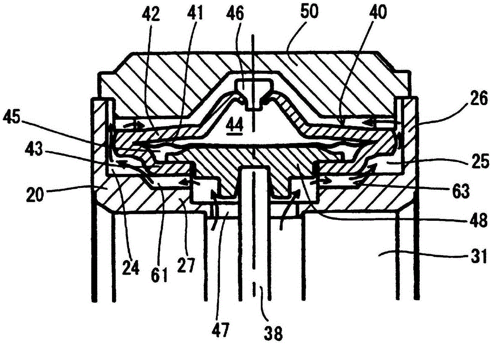
[0030] Next, embodiments of the expansion valve of the present invention will be described with reference to the drawings. figure 1 The expansion valve 1 shown is used in the refrigeration cycle of air conditioners such as automobiles. Inside a square columnar valve body 20 made of aluminum or the like, a first passage 30 is formed at a distance from each other up and down. The first passage 30 is The high-pressure side passage through which the refrigerant passes from the refrigerant outlet of the condenser to the refrigerant inlet of the evaporator through the accumulator; and the second passage 31, which is from the refrigerant outlet of the evaporator to the condenser The path through which the refrigerant at the refrigerant inlet passes.

[0031] A valve chamber 32 and an orifice 33 for adiabatically expanding the refrigerant are formed in the middle of the first passage 30 . In the valve chamber 32 , a spherical valve element 34 is disposed in contact with and separate...


PUM


Abstract

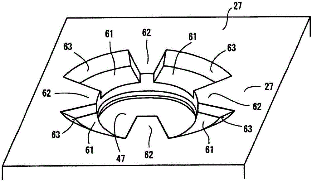
A top-end opening of a closed-end power element containing chamber (24) formed at a top end of valve unit (20) is hermetically sealed in an air-tight state by a closing member (50) fixed by electron beam welding or the like. A power element (40) is fixed sandwiched between a convex portion (53) disposed at a bottom surface of the closing member and a bottom wall (27) of the power element containing chamber. A number of components and a product cost are reduced because screw forming is not necessary for the power element and valve unit, and it is not necessary to dispose a seal member around the power element. A low-pressure refrigerant flowed through a second channel (31) is guided into the power-element containing chamber (24) passing through a penetration hole (47) of the valve unit (20). The power element (40) improves precision of a refrigerant flow-rate control because it is less likely to be affected by an external air temperature with the vicinity being filled with refrigerant. Also, the power-element containing chamber (24) is disposed above the second channel (31) so pressure losses of the low-pressure refrigerant flowed through the second channel (31) is reduced.

Description

technical field [0001] The present invention relates to an expansion valve installed in a refrigeration cycle and controlling the flow rate of refrigerant flowing through an orifice according to the temperature of the refrigerant. Background technique [0002] In the refrigeration cycle of an air-conditioning device mounted on an automobile, a temperature expansion valve with a built-in temperature sensing mechanism is used to make the high-pressure liquid refrigerant from the condenser pass through an orifice to become a low-pressure and It is sent to the evaporator, and through the low-pressure gaseous refrigerant returned from the evaporator to the compressor, the opening of the orifice is controlled according to the temperature and pressure of the gaseous refrigerant, thereby adjusting the passage of the refrigerant (Refer to Patent Document 1). [0003] The expansion valve disclosed in the above-mentioned Patent Document 1 is as follows: Figure 8 As shown, it has: a v...

Claims


Application Information

Patent Timeline
Patent Type & Authority Patents(China)
IPC IPC(8): F25B41/06
CPCF25B41/062F25B2341/0683F25B41/335
Inventor 小林和人吴羽敏道松田亮横田浩
Owner FUJIKOKI MFG CO LTD
Learn More