
Structure and method of making a dual gate device

A gate trench and gate contact technology, which is applied in semiconductor/solid-state device manufacturing, semiconductor devices, electrical components, etc., can solve problems such as low on-resistance and difficult manufacturing

Active Publication Date: 2016-01-06
VISHAY SILICONIX LLC
View PDF3 Cites 0 Cited by
  • Summary
  • Abstract
  • Description
  • Claims
  • Application Information

AI Technical Summary

Problems solved by technology

The split gate structure offers many advantages, including better switching voltage and breakdown voltage, and lower on-resistance, but this structure is difficult to manufacture

Method used


Image

  • Structure and method of making a dual gate device
  • Structure and method of making a dual gate device
  • Structure and method of making a dual gate device

Examples


Embodiment Construction

[0017] In the following detailed description of the invention, numerous specific details are set forth in order to provide a thorough understanding of the invention. It will be appreciated, however, by one skilled in the art that the invention may be practiced without these specific details or with their equivalents. In other instances, well-known methods, procedures, components, and circuits have not been described in detail so as not to unnecessarily obscure aspects of the present invention.

[0018] Some portions of the detailed description below will be expressed in terms of procedures, logical blocks, processes, and other symbolic representations of operations for fabricating a semiconductor device. These descriptions and representations are the means used by those skilled in the art of semiconductor device fabrication to most effectively convey the substance of their work to others skilled in the art. In this application, a procedure, box, process, or the like, is consi...


PUM


Abstract

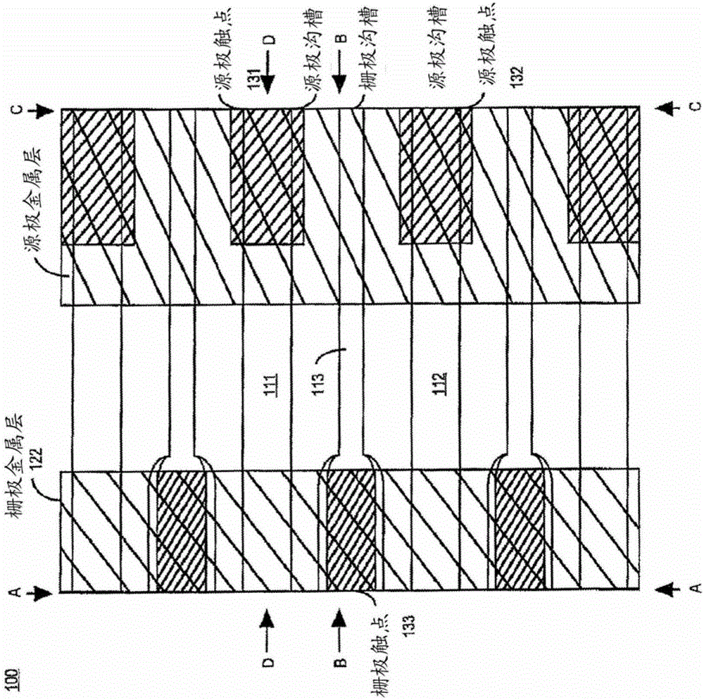
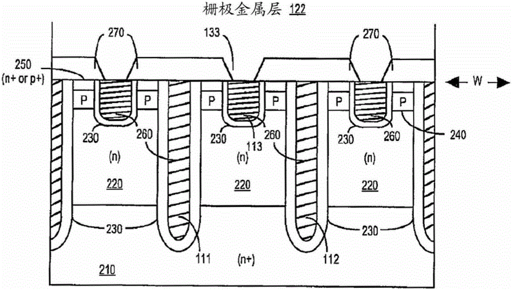
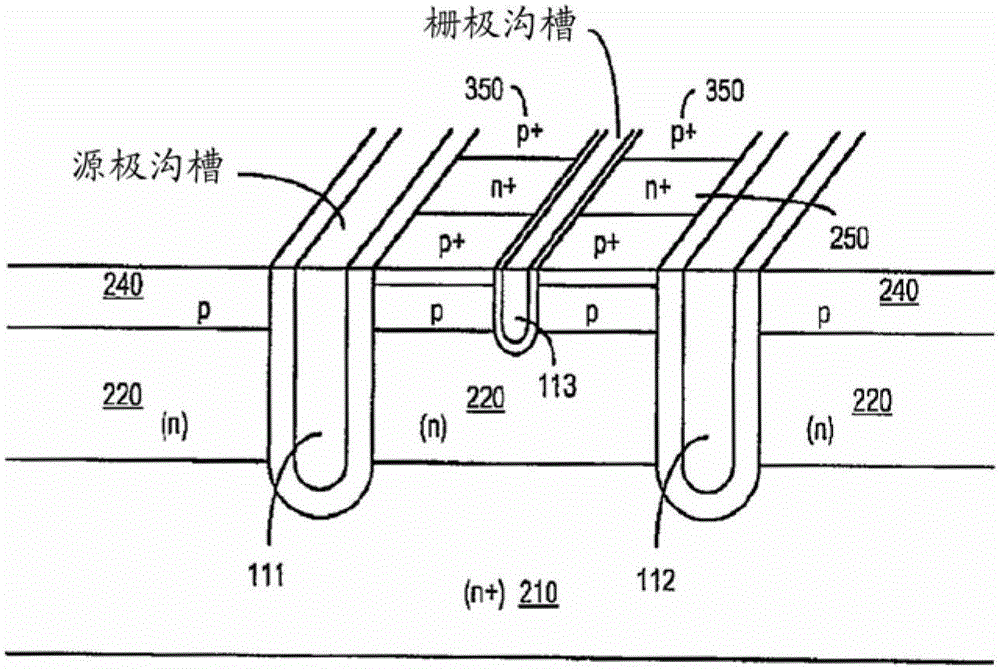
A first polysilicon (polysilicon-1) is deposited into the deep trenches already formed in the substrate. A first polysilicon polishing process is performed to planarize the exposed surface of polysilicon-1 such that the surface is flush with adjacent surfaces. Then, shallow trenches are formed in the substrate between the deep trenches, and a second polysilicon (polysilicon-2) is deposited into these shallow trenches. A second polysilicon polishing process is performed to planarize the exposed surface of polysilicon-2 such that the surface is flush with adjacent surfaces. Then, metal contacts to polysilicon-1 and polysilicon-2 are formed.

Description

[0001] related application [0002] This application claims priority to US Provisional Patent Application Serial No. 61 / 309,824, entitled "Structures and Methods of Fabricating Dual Gate MIS Devices," filed March 2, 2010, which is hereby incorporated by reference in its entirety. Background technique [0003] To save power, it is important to reduce power loss in transistors. In Metal Oxide Semiconductor Field Effect Transistor (MOSFET) devices, power loss can be reduced by reducing the device's drain-to-source on-resistance. [0004] To achieve high breakdown voltages in MOS devices, the epitaxial (epi) layer and / or resistivity can be increased, but this can adversely affect on-resistance. To alleviate this problem, a modulated electric field can be introduced perpendicular to the direction of current flow when the device is off. The modulated electric field in the drift region increases the breakdown voltage and allows higher doping concentrations for a given breakdown vol...

Claims


Application Information

Patent Timeline
Patent Type & Authority Patents(China)
IPC IPC(8): H01L29/78H01L21/336
CPCH01L29/407H01L29/41741H01L29/4238H01L29/66734H01L29/7813H01L29/42344H01L21/31053H01L21/3212H01L29/4916
Inventor K.特里尔白玉明D.N.帕塔纳雅克罗志云
Owner VISHAY SILICONIX LLC
Learn More