
Method for quickly measuring blade surfaces by inductive measuring instrument

An inductance and blade technology, applied in electromagnetic measurement devices, electric/magnetic profile/curvature measurement, instruments, etc., can solve the problems of difficult manufacturing of standard parts, long manufacturing cycle, etc., to eliminate the long process preparation cycle and manufacturing The effect of cost reduction and enhanced quality assurance capability

Inactive Publication Date: 2013-01-02
SHENYANG LIMING AERO-ENGINE GROUP CORPORATION
View PDF4 Cites 10 Cited by
  • Summary
  • Abstract
  • Description
  • Claims
  • Application Information

AI Technical Summary

Problems solved by technology

[0003] The purpose of the present invention is to solve the problem that the standard part is difficult to manufacture and the manufacturing cycle is long when the current blade profile is detected by the inductance meter detection method, and the reasonable idea of ​​the improved design of the standard part structure and the standard part precision adjustment method The design greatly reduces the difficulty of manufacturing standard parts and the constraints of the manufacturing cycle, improves the rapid response ability of the method, and makes it easier for the functional advantages of the method to be maximized through the wide application of the method.

Method used


Image

  • Method for quickly measuring blade surfaces by inductive measuring instrument
  • Method for quickly measuring blade surfaces by inductive measuring instrument
  • Method for quickly measuring blade surfaces by inductive measuring instrument

Examples


Embodiment 1

[0037] This embodiment provides a method for quickly realizing the detection of the profile surface of the blade by the inductance meter, which is characterized in that: the method for quickly realizing the detection of the profile surface of the blade by the inductance meter is as follows:

[0038] Preparation:

[0039] First, implement the measurement of the blade structure

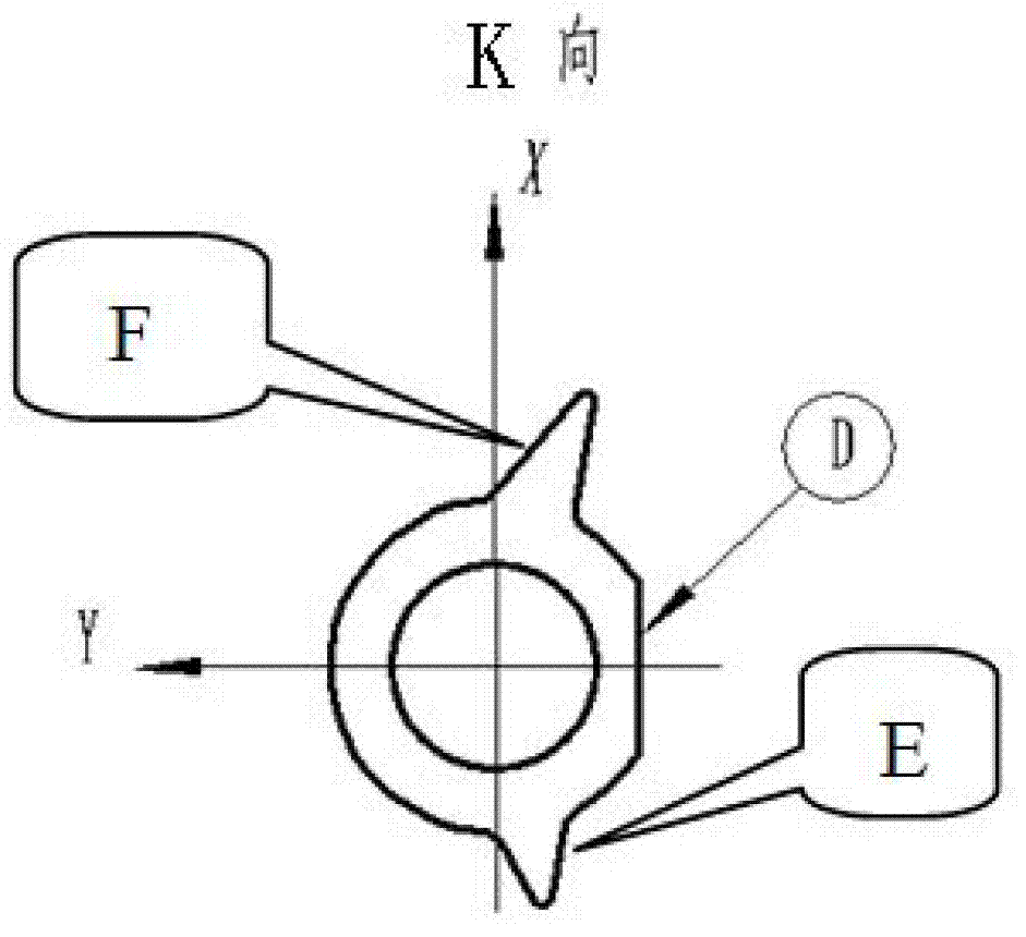
[0040] In the blade structure where the measurement is carried out, the blade measurement and positioning references are the tip holes A and B on the front and rear journal end faces, the outer end surface C of the blade front end edge plate, and the angular positioning plane D of the blade front end edge plate; the measurement compression part is B , D;

[0041] Second, the standard part structure used for blade measurement

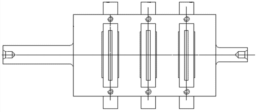
[0042]The standard part structure used for the blade measurement is shown in the attached figure. The standard part of the blade includes the reference frame, the curved surface...


PUM


Abstract

A method for quickly measuring blade surfaces by an inductive measuring instrument particularly includes firstly, adjusting the position of a measurer and the position of a measuring contactor; secondly, measuring combined errors of a standard part, creating references based on the center of a front journal, the center of a rear journal, the front end surface and side planes of a reference frame by a three-coordinate measuring machine, respectively measuring three suction surface or pressure surface sample plates according to specified point positions, and using differences between measured values and data values given by a design drawing as combined error values of suction surface or pressure surface sides; thirdly, adjusting an initial measuring zero position of the inductive measuring instrument, and starting zeroing setting for a suction surface or pressure surface by software functions; fourthly, correcting the zero position to eliminate the combined error values of the combined standard part; and fifthly, measuring a blade. The method has the advantages that the integral standard part of the traditional complex three-dimensional curve blade surface is simplified into a split structure beneficial to machining and manufacturing, manufacturing difficulty for the standard part is greatly reduced, manufacturing cycle is shortened, cost is low, precision is high, and measurement efficiency is greatly improved.

Description

technical field [0001] The invention relates to the field of processing and detection technology, in particular to a method for quickly realizing the detection of blade profiles by an inductance meter. Background technique [0002] At present, the machining accuracy requirements of the blade profiles of aero-engines and gas turbine compressors are getting higher and higher, and the development cycle of new machine blades is getting shorter and shorter. , with faster efficiency and convenience, and at the same time, the process preparation must have a faster response capability. The detection and monitoring of the blade surface has always been a key and important link in the blade manufacturing process. Among them, the detection method of the inductance meter has always been the most important part of the blade surface processing because of its high detection accuracy, fast detection speed, and convenient operation. It is an effective method that is expected to be widely use...

Claims


Application Information

Patent Timeline
IPC IPC(8): G01B7/00G01B7/28
Inventor 刘随建刘建伟曹颖志张士雷宋成
Owner SHENYANG LIMING AERO-ENGINE GROUP CORPORATION
Learn More