
Microshell vibrating gyroscope and preparation method thereof

A technology for vibrating gyroscopes and shells, which is applied to gyroscopes/steering sensing equipment, gyro effects for speed measurement, and measurement devices. It can solve the problems of difficult to achieve arc surface capacitance processing, low driving and detection efficiency, and small capacitance area. problems, to achieve the effects of simplifying the mode and frequency trimming process, improving the processing accuracy and structural symmetry of the three-dimensional curved surface, and simplifying the processing technology

Active Publication Date: 2018-06-22
NAT UNIV OF DEFENSE TECH
View PDF6 Cites 0 Cited by
  • Summary
  • Abstract
  • Description
  • Claims
  • Application Information

AI Technical Summary

Problems solved by technology

Although the in-plane working method of the arc surface working electrode can greatly increase the area of ​​the driving and detection electrodes, it is difficult to realize the machining of the arc surface capacitance with micro-scale high-precision electrode gap due to the limitation of the current three-dimensional micromachining technology.
Based on the out-of-plane working mode of the parallel plate working electrode, the electrode gap is easy to ensure and the consistency is good, but the capacitance area is relatively small, and the driving and detection efficiency is low

Method used


Image

  • Microshell vibrating gyroscope and preparation method thereof
  • Microshell vibrating gyroscope and preparation method thereof
  • Microshell vibrating gyroscope and preparation method thereof

Examples


Embodiment 1

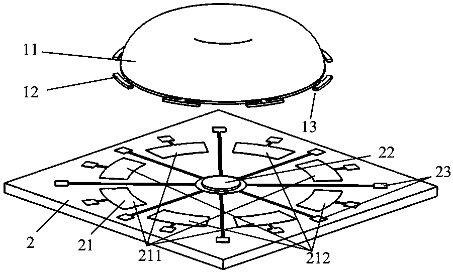
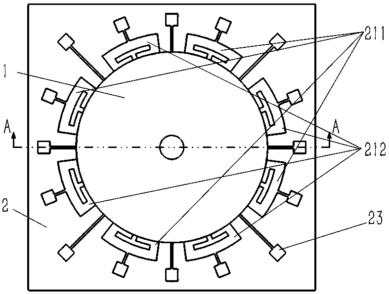
[0039] Such as Figure 1 to Figure 5 The embodiment of the microshell vibrating gyroscope of the present invention is shown, the microshell vibrating gyroscope includes a microshell gyro resonator 1 and a glass substrate 2, the microshell gyro resonator 1 is arranged on the glass substrate 2, and the microshell The bulk gyro resonator 1 includes a rotary housing 11 and a plurality of sensitive mass elements 12, the plurality of sensitive mass elements 12 are evenly distributed on the outer circumference of the bottom of the rotary housing 11, and the rotary housing 11 and the plurality of sensitive mass elements 12 are opposite to the glass A metal film 13 is provided on the surface of the substrate 2 , and the glass substrate 2 includes a plurality of fixed capacitor plates 21 corresponding to a plurality of sensitive mass elements 12 on the plurality of fixed capacitor plates 21 . There is a gap between each fixed capacitor plate 21 and its corresponding sensitive mass eleme...


PUM


Abstract

The invention discloses a micro shell vibration gyroscope and a preparation method thereof. The micro shell vibration gyroscope comprises a micro shell gyroscope harmonic oscillator and a glass substrate. The micro shell gyroscope harmonic oscillator is arranged on the glass substrate; the micro shell gyroscope harmonic oscillator comprises a rotating shell and a plurality of sensitive mass components; the sensitive mass components are uniformly distributed on the periphery of the bottom of the rotating shell; metal films are arranged on surfaces of the rotating shell and the plurality of sensitive mass components, which are opposite to the glass substrate; the glass substrate comprises a plurality of fixed capacitor plates; the plurality of fixed capacitor plates correspond to the plurality of sensitive mass components. The preparation method comprises: preparing the micro shell gyroscope harmonic oscillator by a high-accuracy contact pattern; carrying out micro assembling. The micro shell vibration gyroscope carries out driving and detection based on out-of-plane, and has the advantages of convenience in machining, high machining accuracy, high driving and detecting efficiency, convenience in mode and frequency trimming, good robustness, low cost and the like. The preparation method can greatly improve surface form machining accuracy of a three-dimensional curved surface and structural symmetry of the micro shell gyroscope harmonic oscillator.

Description

technical field [0001] The invention belongs to the field of micro-mechanical sensors, in particular to a vibrating gyroscope with a micro-shell and a preparation method thereof. Background technique [0002] The gyroscope is a sensor that measures the rotational motion of the carrier relative to the inertial space. It is the core device in the fields of motion measurement, inertial navigation, guidance and control, etc. It plays a very important role in high-end industrial equipment and precision strike weapons such as aerospace, intelligent robots, and guided munitions. Value. [0003] At present, based on micromachining technology, batch processing of sensors can be realized on wafers, and the processing of micro gyroscopes with small size, low cost and low power consumption has been realized. After years of development, the accuracy of MEMS gyroscopes has reached the rate level, and it has a wide range of applications in the automotive and consumer electronics fields (t...

Claims


Application Information

Patent Timeline
IPC IPC(8): G01C19/567
CPCG01C19/567
Inventor 肖定邦吴学忠侯占强李微陈志华吴宇列卢坤石岩
Owner NAT UNIV OF DEFENSE TECH
Learn More