
Substrate-precise-positioning workpiece stage

A technology of precise positioning and workpiece table, which is applied to the photoplate making process of the work table, pattern surface, and manufacturing tools, etc. It can solve the problems of high overall cost and complex CCD mechanical structure, and achieve the effect of high alignment accuracy.

Active Publication Date: 2012-12-26
SHANGHAI MICRO ELECTRONICS EQUIP (GRP) CO LTD
View PDF3 Cites 21 Cited by
  • Summary
  • Abstract
  • Description
  • Claims
  • Application Information

AI Technical Summary

Problems solved by technology

Since the visual range of the CCD of the machine vision system for optical measurement has certain requirements, it is necessary to perform a preliminary pre-alignment operation on the substrate before it is uploaded to the workpiece table. At the same time, due to the complicated mechanical structure of the CCD, relevant image acquisition and control are required. Processed boards, the overall cost is relatively high

Method used


Image

  • Substrate-precise-positioning workpiece stage
  • Substrate-precise-positioning workpiece stage
  • Substrate-precise-positioning workpiece stage

Examples


Embodiment Construction

[0012] Specific embodiments of the present invention will be described in detail below in conjunction with the accompanying drawings.

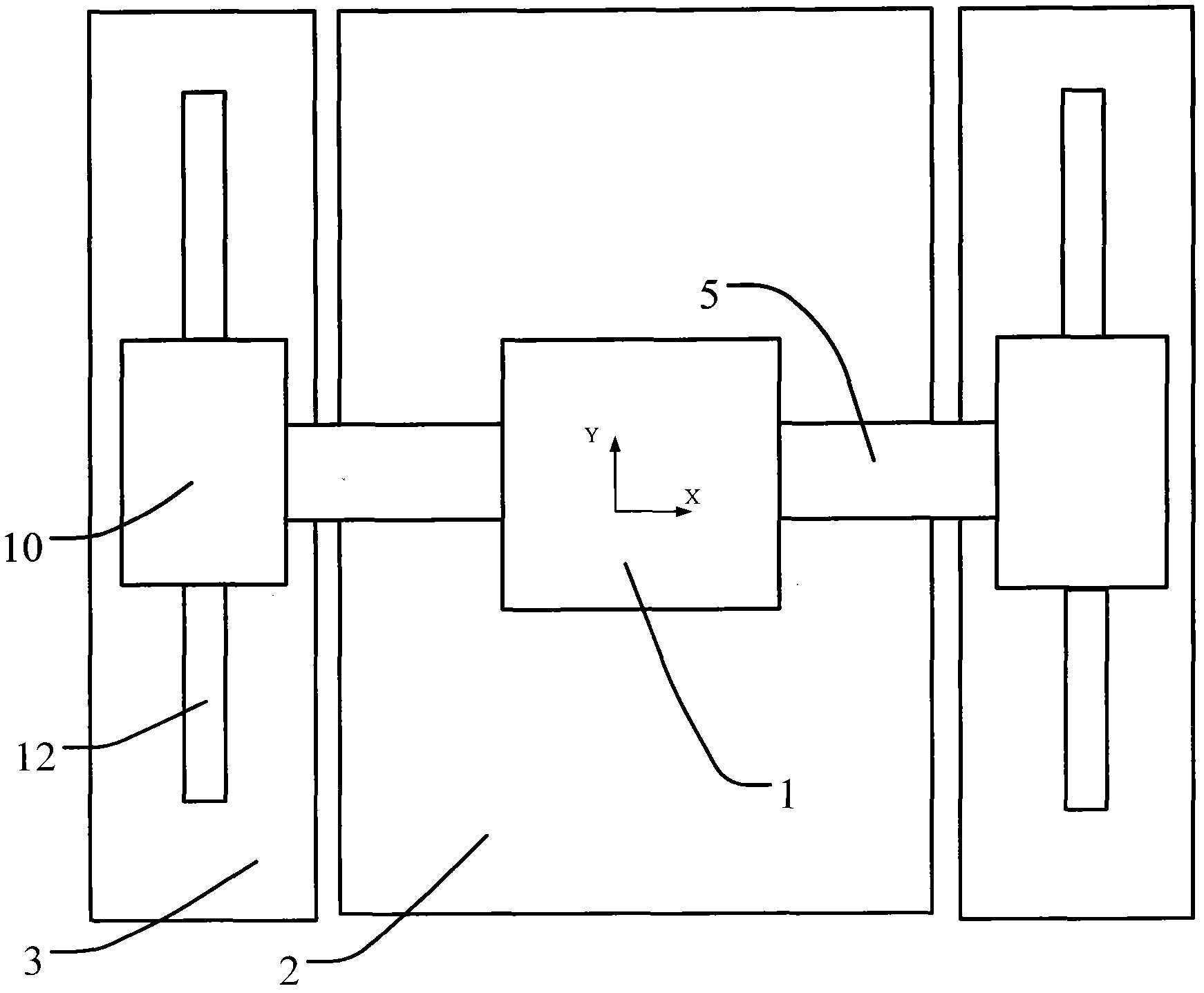
[0013] Such as figure 1 As shown, the workpiece table 1 is straddled on the X-guiding rail 5, and the two sides are respectively connected laterally with the X-guiding rail 5 by air bearings, and the bottom is also connected to the smooth platform 2 by using the air bearings. The use of air bearings can achieve frictionless relative movement. A drive device (not shown in the figure) is installed inside the workpiece table 1, such as a mover of a linear motor, and a corresponding stator is installed on the X guide rail 5. Using the drive device Realize the linear reciprocating motion in the X direction. At the same time, the mover is installed in the Y-direction drive device 10, and the corresponding stator 12 is installed on the Y-direction rail 3. The drive device is used to realize the linear reciprocating motion in the Y direction, and the...


PUM


Abstract

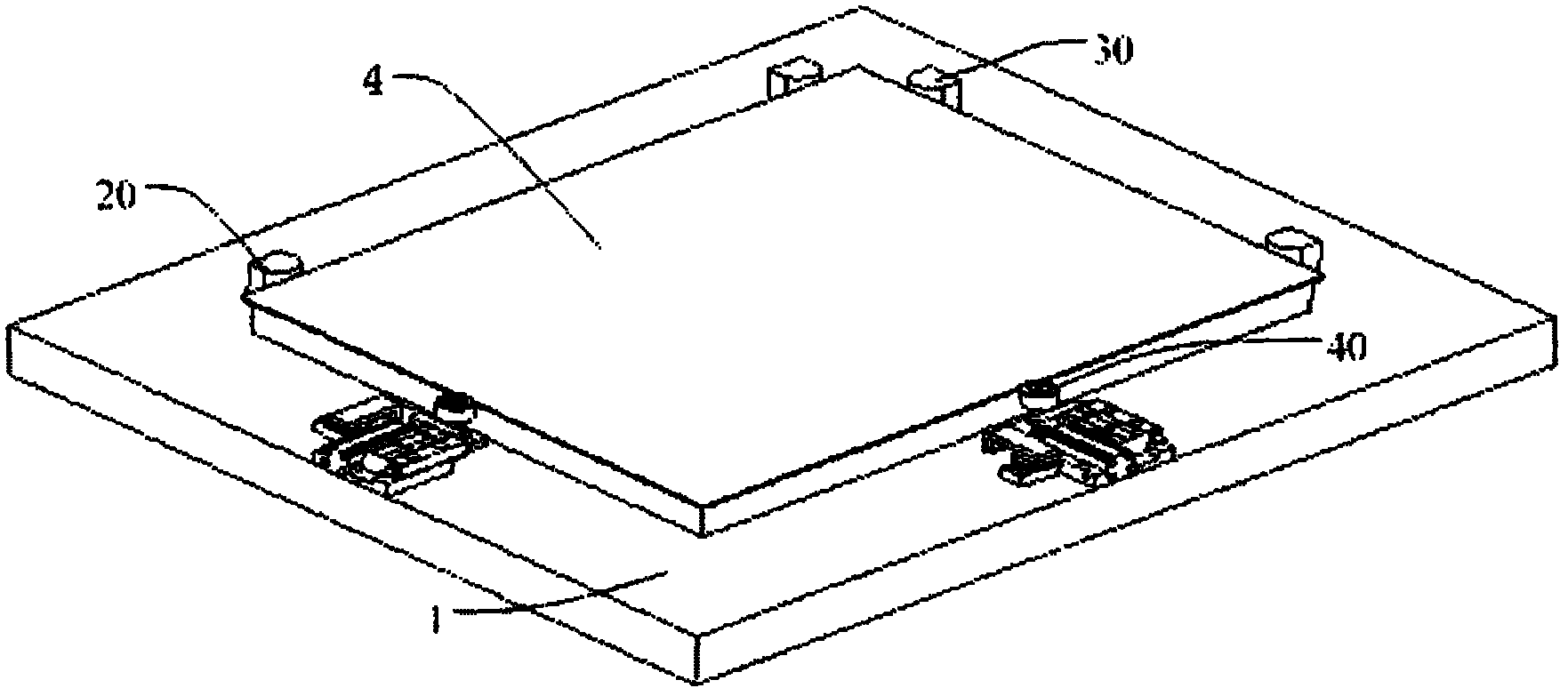
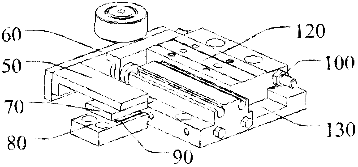
The invention relates to a substrate-precise-positioning workpiece stage which is characterized in that X-direction and Y-direction fixed positioning elements and a mobile bearing positioning element are arranged on the workpiece stage. A sensor is arranged on the mobile bearing positioning element, such that substrate arrangement position deviation can be measured instantly. According to the workpiece stage that can carry out a pre-alignment operation upon the substrate, substrate pre-alignment operation can be rapidly and simply carried out directly on the workpiece stage, and an alignment precision is high. A repetitive positioning accuracy can reach a micrometer-level.

Description

technical field [0001] The invention relates to the technical field of semiconductor manufacturing, in particular to a work table used for precise positioning of a substrate in a photolithography device. Background technique [0002] In a lithography device, when a glass substrate is loaded onto a workpiece stage, the glass substrate has an ideal position required. However, in the actual operation process, the glass substrate will have certain eccentricity and deviation compared with the ideal position. Usually, it is necessary to calculate the eccentricity and deviation value of the substrate at P to adjust the position of the substrate carrier. In order to determine the position of the actual center of the glass substrate, a machine vision system CCD based on optical measurement is used inside the lithography machine to realize the positioning of the glass substrate, that is, CCD1 and CCD2 located on both sides of the substrate are used to determine the eccentricity value ...

Claims


Application Information

Patent Timeline
Patent Type & Authority Applications(China)
IPC IPC(8): G03F7/20G03F9/00B25H1/08
Inventor 黄剑飞郭鹏
Owner SHANGHAI MICRO ELECTRONICS EQUIP (GRP) CO LTD
Learn More