
Strain design based economical pipe line steel and its manufacturing method

A technology for pipeline steel and manufacturing methods, applied in the direction of temperature control, etc., can solve the problems of extending rolling time, reducing production efficiency, and low rolling temperature, so as to improve rolling efficiency, reduce production cost, and reduce relaxation time Effect

Active Publication Date: 2012-12-19
ANGANG STEEL CO LTD
View PDF9 Cites 28 Cited by
  • Summary
  • Abstract
  • Description
  • Claims
  • Application Information

AI Technical Summary

Problems solved by technology

However, the current X80 grade pipeline steel is a typical less pearlite or acicular ferrite structure. The performance of the steel plate corresponding to this structure type has good strength and toughness matching, but its plasticity is insufficient, and the uniform deformation elongation rate UEL Not more than 10%, the yield ratio is mostly above 0.85, and some even reach 0.92
The pipeline steel produced by the traditional TMCP process cannot meet the material selection criteria based on the strain design method
[0005] At present, the research on pipeline steel based on strain design has been reported at home and abroad, but there are the following problems: For example, patents US5545270A and US5531842 provide the composition and manufacturing method of X80 and above duplex pipeline steel, and both patents add Mo , V elements, and three-stage rolling of the steel billet is required, and the intermediate billet is rolled twice to wait for temperature, which prolongs the rolling time and reduces the production efficiency. In addition, it needs to be rolled in the two-phase area, and the rolling temperature is low. Rolling resistance Large, high requirement for rolling mill capacity

Method used


Image

  • Strain design based economical pipe line steel and its manufacturing method
  • Strain design based economical pipe line steel and its manufacturing method
  • Strain design based economical pipe line steel and its manufacturing method

Examples


Embodiment Construction

[0035] The present invention will be further described below by way of examples.

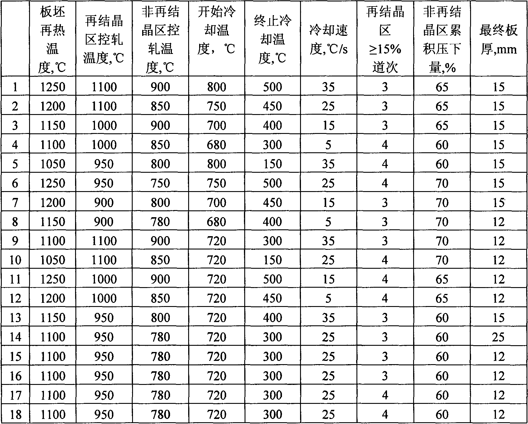
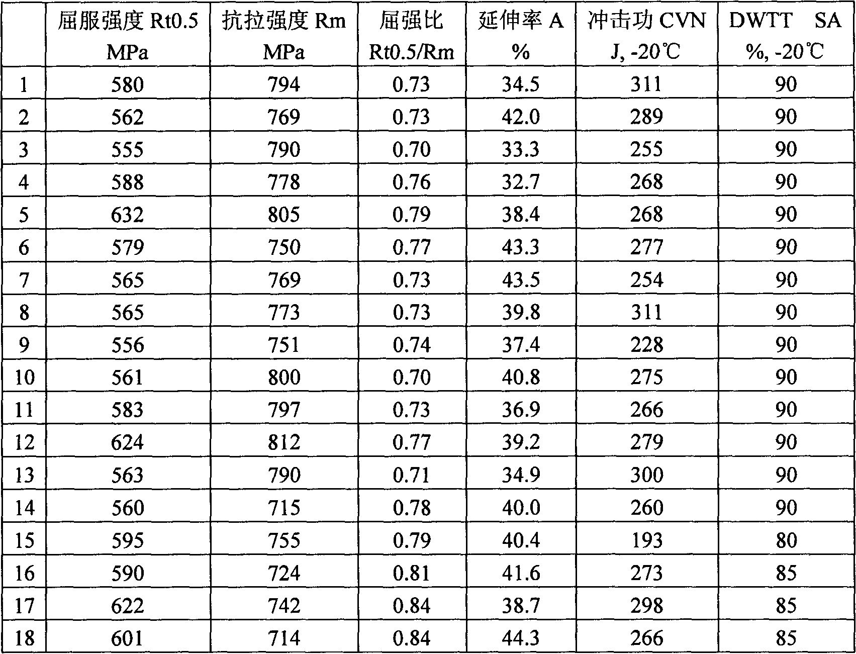
[0036] The chemical composition (wt%) of the steel of the embodiment of the present invention is shown in Table 1, 1-14 in the table is the embodiment of the present invention, and 15-18 is the comparative example.

[0037] Table 1 The chemical composition of the embodiment steel of the present invention

[0038]

C

Si

mn

P

S

Ti

Nb

V

Cu

Ni

Cr

Mo

Al

1

0.06

0.30

1.70

0.01

0.003

0.017

0.03

0

0.22

0.23

0.20

0

0.04

2

0.06

0.25

1.65

0.01

0.003

0.012

0.04

0

0.15

0.17

0.16

0

0.03

3

0.07

0.40

1.60

0.01

0.003

0.015

0.03

0

0

0.40

0.11

0

0.03

4

0.07

0.35

...


PUM


Abstract

The invention provides strain design based economical pipe line steel and its manufacturing method. The steel comprises the following ingredients of: by weight, 0.06-0.10% of C, 0.1-0.6% of Si, 1.0-2.0% of Mn, P being less than or equal to 0.015%, S being less than or equal to 0.003%, 0.1-0.3% of Cr, 0.01-0.10% of Nb, 0.005-0.03% of Ti, 0.01-0.06% of Al, N being less than or equal to 0.012%, 0-0.5% of Cu, 0-0.5% of Ni and the balance being Fe. The method provided by the invention comprises steps of smelting, secondary refining, casting and hot rolling, and is characterized in that slab heating temperature is 1050-1280 DEG C; controlled rolling temperature in a recrystallization zone is 900-1250 DEG C; controlled rolling temperature in a non-recrystallization zone is 750-950 DEG C; initial cooling temperature is 680-800 DEG C; finish cooling temperature is 100-500 DEG C; and cooling rate is 5-35 DEG C / s. According to the invention, elements of Mo, V, B and the like are not added, and the total amount of Cu, Cr and Ni is low. In addition, subsequent heat treatment is not required, the process is simple and requires low cost, and production efficiency is high. The steel plate not only has high strength but also has low yield ratio and high uniform extension features. By the adoption of the steel, safety of pipeline operation and economy of pipeline construction can be greatly raised.

Description

technical field [0001] The invention belongs to the technical field of steel for pipelines, in particular to an economical steel for pipelines based on strain design and a manufacturing method thereof. The pipeline steel prepared by applying the present invention can be applied to the steel for pipelines using X80 and above steel grades in polar regions, permafrost zones, seismic zones and seabeds. Background technique [0002] In recent years, the change of energy structure and the growth of demand for energy have greatly promoted the exploration and exploitation of new oil and gas resources. Most of the large-reserve oil and gas fields discovered so far are located in areas with special geological conditions such as polar regions, permafrost zones, seismic zones, and deep seas. In the large-scale movement of strata or ocean currents in these areas, the pipeline steel must not only bear high internal pressure, but also must have a relatively high deformation capacity and s...

Claims


Application Information

Patent Timeline
IPC IPC(8): C22C38/38C22C38/28C22C38/58C22C38/50B21B37/74
Inventor 刘文月任毅张帅张禄林王爽王晓强宁东隋轶
Owner ANGANG STEEL CO LTD
Learn More