
Coil-well resident building elevator

A pan-well type and elevator technology, which is applied to elevators, elevators, hoisting devices, etc. in buildings, can solve problems that are not suitable for multi-storey buildings, large building areas, and difficult installation and use, so as to prevent personal injury and death accidents, Check the effect of easy maintenance and repair, low running speed

Inactive Publication Date: 2012-12-19
余载强
View PDF7 Cites 13 Cited by
  • Summary
  • Abstract
  • Description
  • Claims
  • Application Information

AI Technical Summary

Problems solved by technology

[0002] At present, passenger elevators in the world can be roughly divided into two types according to different places of use. One type is the step-type automatic elevator in stations, shopping malls, hotels and other places that must continuously transport a large number of passengers. The building area is large and the cost is high. The other type is the vertical elevator with fewer passengers and more landing points. Almost all high-rise and small high-rise buildings use this type of elevator. This type of elevator must occupy the building area and set up special The elevator shaft is used as the elevator channel; considering the construction and operation costs and the area occupied by the elevator channel, these two elevators are generally not suitable for multi-storey buildings; it is even more difficult to install and use in a large number of multi-storey buildings without elevators

Method used


Image

  • Coil-well resident building elevator
  • Coil-well resident building elevator
  • Coil-well resident building elevator

Examples


Embodiment Construction

[0054] Below in conjunction with embodiment and accompanying drawing, the panjing type private building elevator of the present invention is described in detail.

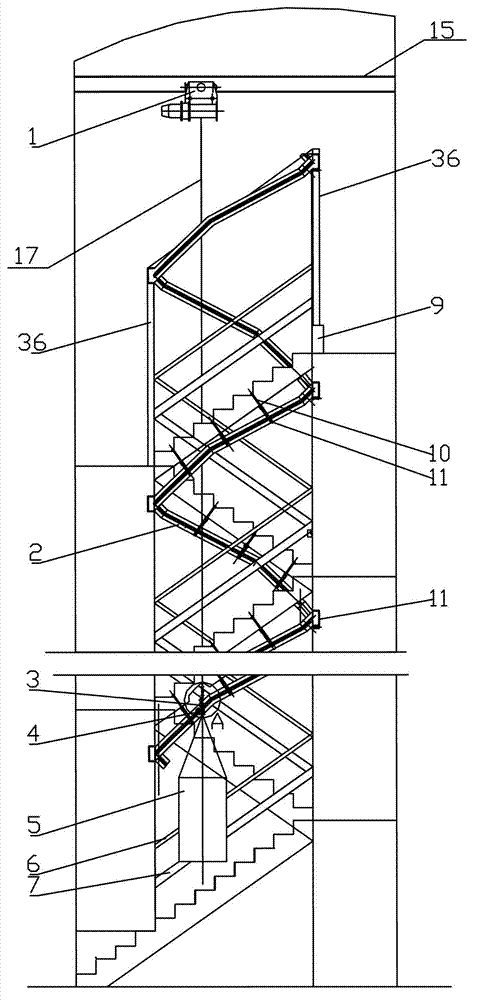
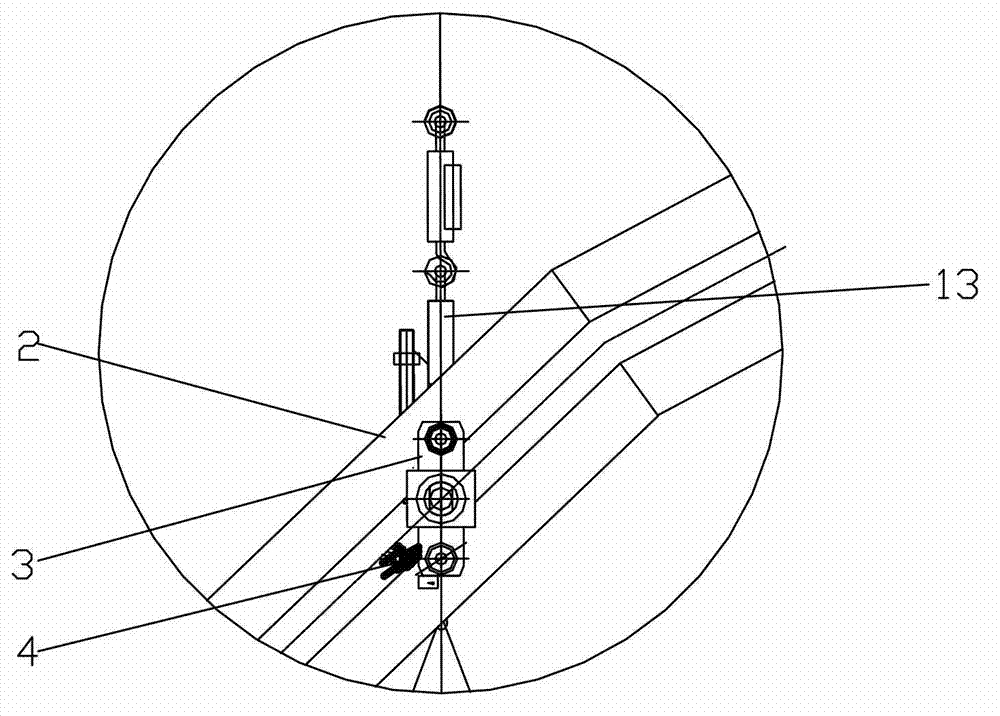
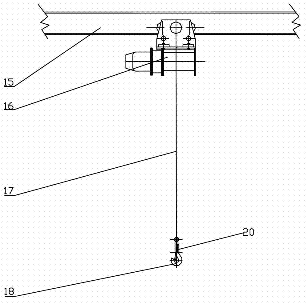
[0055] Panjing formula civil building elevator of the present invention, as figure 1 , figure 2As shown, it includes: rail beam 15, which is arranged under the top roof panel on the uppermost floor of the central surface of the stairwell, and is arranged horizontally; lifting device 1, which is movably arranged on rail beam 15; lifting rope 17, whose upper end is connected with the The device 1 is connected, and the lower end is connected with a hook 18; the track device 2, the track device 2 is installed on the lower edge of the stair plate above the stair railing 6 or on the inner side of the stair plate, and the top part is fixed by the bracket 36 , the bracket 36 is positioned on the stair railing 6 and the railing column; the slideway 7 is arranged on the outside of the railing column below the stair railing ...


PUM


Abstract

The invention discloses a coil-well resident building elevator. The coil-well resident building elevator is provided with a track beam, a lifting-pulling device, a lifting-pulling rope, a track device, a slideway, a pulley device, a manned device and a braking mechanism, wherein the track beam is arranged below a roof panel on a topmost layer on the upper part of the central surface of a stair wheel; the lifting-pulling device is movably arranged on the track beam; the upper end of the lifting-pulling rope is connected with the lifting-pulling device; the track device is arranged on the lower edge of a stair board above a stair railing or on the inner side face of the stair board around the stair well; brackets are positioned on the stair railing and a railing upright post; the slideway is arranged on the outer side of the raining upright post below the stair railing; the pulley device is movably arranged on the track device; the manned device is connected to the lower end of the pulley device; the side face of the manned device is connected with the slideway in a sliding way; and the braking mechanism is arranged between the pulley device and the track device, and is used for braking the pulley device and stopping the elevator under the control of a brake handle and a control device. The coil-well resident building elevator has the advantages of no need of any special channel, no occupation of the building area, simple equipment, convenience in installing and low cost on building and running, and is suitable for multi-story buildings, in particular for built powerless multi-floor buildings.

Description

technical field [0001] The present invention relates to an elevator. In particular, it relates to a panwell type civil building elevator which is used to be arranged in multi-storey buildings and built-up multi-storey buildings without elevators. Background technique [0002] At present, passenger elevators in the world can be roughly divided into two types according to different places of use. One type is the step-type automatic elevator in stations, shopping malls, hotels and other places that must continuously transport a large number of passengers. The building area is large and the cost is high. The other type is the vertical elevator with fewer passengers and more landing points. Almost all high-rise and small high-rise buildings use this type of elevator. This type of elevator must occupy the building area and set up special The elevator shaft is used as the elevator passage; considering the building and operating costs and the elevator passage occupying an area, the...

Claims


Application Information

Patent Timeline
Patent Type & Authority Applications(China)
IPC IPC(8): B66B9/08B66B11/04B66B11/02B66B7/02B66D5/30
Inventor 余载强余晓丹贾宏杰
Owner 余载强
Learn More