Direct-evaporation temperature and humidity exchange air-conditioning system

An air conditioning system, temperature and humidity technology, applied in air conditioning systems, heating and ventilation control systems, heating and ventilation safety systems, etc. and other problems, to achieve the effect of energy saving and water saving, reducing labor intensity and saving energy consumption

Inactive Publication Date: 2012-12-12
马利娜
View PDF5 Cites 0 Cited by
  • Summary
  • Abstract
  • Description
  • Claims
  • Application Information

AI Technical Summary

Problems solved by technology

[0004] In CN201302256Y, a constant temperature and humidity variable air volume control system for textile air conditioners is disclosed. Windshield actuators, temperature and humidity sensors, and host computers, etc., have the disadvantage that the above-mentioned controls will be delayed, and the humidity and humidity in the workshop cannot be quickly adjusted in a relatively short period of time. It is difficult to ensure the stability of product quality, and the power consumption Big

Method used


Image

  • Direct-evaporation temperature and humidity exchange air-conditioning system
  • Direct-evaporation temperature and humidity exchange air-conditioning system
  • Direct-evaporation temperature and humidity exchange air-conditioning system

Examples


Embodiment 1

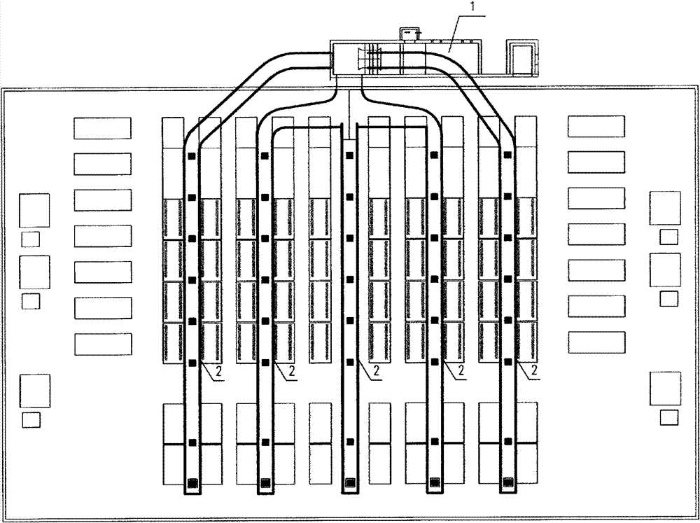
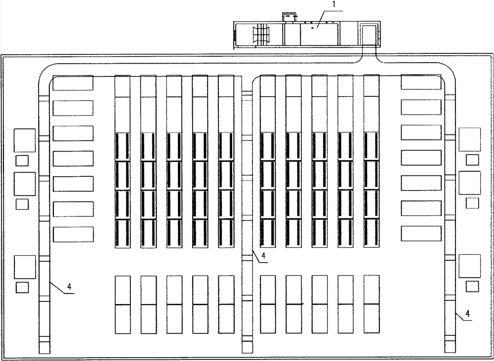
[0042] refer to Figure 1-Figure 5 , the direct evaporative temperature-humidity exchange air-conditioning system of the present invention comprises the air-conditioning room 1 made up of the air supply chamber 111, the spray chamber 112 and the return air chamber 113 and the air supply pipe 2, the air supply port 106 and the upper return air pipe 3, The air supply and return system formed by the ground return air pipe 4 and the air return port 107, wherein a blower 101 is installed between the air supply chamber 111 and the spray chamber 112 (the air volume is calculated as the number of air changes is not greater than 8 times per hour), In the spray room, respectively install water baffles 102, one or two groups of controllable spray pipes 103, and install 2 to 3 rows of nozzles 104 in each group, and the number of nozzles is 3-5 per m 2 The air supply chamber 111 sends wet and cold air into the work area through the air supply pipe 2 and the air supply port 106 located at t...

Embodiment 2

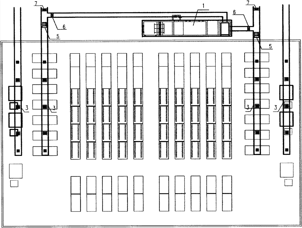
[0044] A cut-off valve 6 and an exhaust valve 7 are arranged between the upper return air pipe 3 and the return air chamber. In summer, the stop valve 6 can be closed and the exhaust valve 7 can be opened to discharge hot air; in winter, the exhaust valve 7 can be closed. Open the cut-off valve 6 to allow hot air to enter the return air chamber 113, so as to make full use of the original waste heat, thereby omitting the heater in the traditional air-conditioning system, and improving the energy-saving efficiency of the air-conditioning system. A blower fan 5 is arranged in the air supply pipe 2 or the air return pipe 3, which can be opened as required to facilitate normal work in high temperature climates. The feng-shui ratio is appropriate, and the circulating water does not heat up, thus achieving the purpose of water saving. The air supply outlet is preferably located above the working area of ​​the equipment, so that the wet and cold air can exchange temperature and humidi...


PUM


Abstract

A direct-evaporation temperature and humidity exchange air-conditioning system comprises an air-conditioning chamber and an air feed and return system, wherein the air-conditioning chamber consists of an air feed chamber, a spray chamber and an air return chamber, and the air feed and return system comprises air feed pipes, an air feed inlet, air return pipes and an air return inlet. An air blower is mounted between the air feed chamber and the spray chamber, a water baffle, spray pipes and spray nozzles are mounted in the spray chamber, and the air feed chamber feeds cold and humid air into a working area through the air feed pipes and the air feed inlet on the upper portion of the working area. The spray pipes are modified to be arranged in 2-6 rows, ground air return pipes are arranged under the ground of the working area, upper air return pipes are arranged above the working area, an air return fan in the air return chamber and the air return inlet and a disc type filter screen on the wall of a workshop are omitted, so that the integral system runs circularly and naturally by air density difference, and temperature and humidity can be dynamically balanced. The direct-evaporation temperature and humidity exchange air-conditioning system has the advantages of few air exchange times, low water consumption and power consumption and proper temperature and humidity in the workshop, static electricity during technical process of products can be avoided, and off-machine moisture regain of cashmere can reach 18% and the like.

Description

technical field [0001] The invention relates to a direct evaporative temperature-humidity exchange air-conditioning system, in particular the evaporative temperature-humidity exchange air-conditioner system which is especially suitable for carding workshops. Background technique [0002] The existing air-conditioning system, especially the evaporative temperature-humidity exchange air-conditioning system suitable for carding workshops, consists of an air supply chamber, a spray chamber and a return air chamber, wherein a blower is installed between the air supply chamber and the spray chamber. , there are water baffles, spray pipes, nozzles and heaters installed in the spray room. The spray pipes are generally arranged in ten rows, and each row has more than 200 nozzles (equivalent to 30-40 nozzles per square meter) ), the spray pipe is connected to the reservoir through the water supply pipe and the return pipe, a return fan is installed in the return air chamber, and a fil...

Claims


Application Information

Patent Timeline
Patent Type & Authority Applications(China)
IPC IPC(8): F24F5/00F24F11/02F24F13/02F24F13/06F24F13/28
Inventor 李毅武可成马利娜祁崇涛
Owner 马利娜
Why Eureka
Try Eureka