
Intelligent locking valve

An intelligent locking and valve closing technology, applied in the field of valves and ball valves, can solve the problems of undiscovered patent documents, reduced valve sealing performance, limited wear resistance of coatings, etc., to solve the problem of contact wear, eliminate wear, prolong The effect of service life

Inactive Publication Date: 2012-12-12
TIANJIN BAILIZHANFA GRP
View PDF6 Cites 0 Cited by
  • Summary
  • Abstract
  • Description
  • Claims
  • Application Information

AI Technical Summary

Problems solved by technology

[0002] The valves used in the working conditions of more solid granular media are very easy to wear and have a short service life during the switching process. The sealing surface is jammed by granular media and the switching torque is very large. In order to prolong the service life of the valve and be jammed by granular media, it is usually The best way is to set a wear-resistant hard coating on the sealing surface of the valve core and valve seat, and set a scraper to remove particles.
Due to the unavoidable contact wear during the switching process, the wear resistance of the coating is limited, and the service life is short. The scraper cannot remove small particles, which leads to wear of the sealing surface of the valve core and valve seat, which reduces the sealing performance of the valve and shortens the service life.
[0003] Through searching, no published patent documents identical with the application of the present invention have been found

Method used


Image

  • Intelligent locking valve
  • Intelligent locking valve
  • Intelligent locking valve

Examples


Embodiment Construction

[0017] The present invention will be further described in detail below in conjunction with the accompanying drawings and through specific embodiments. The following embodiments are only descriptive, not restrictive, and cannot limit the protection scope of the present invention.

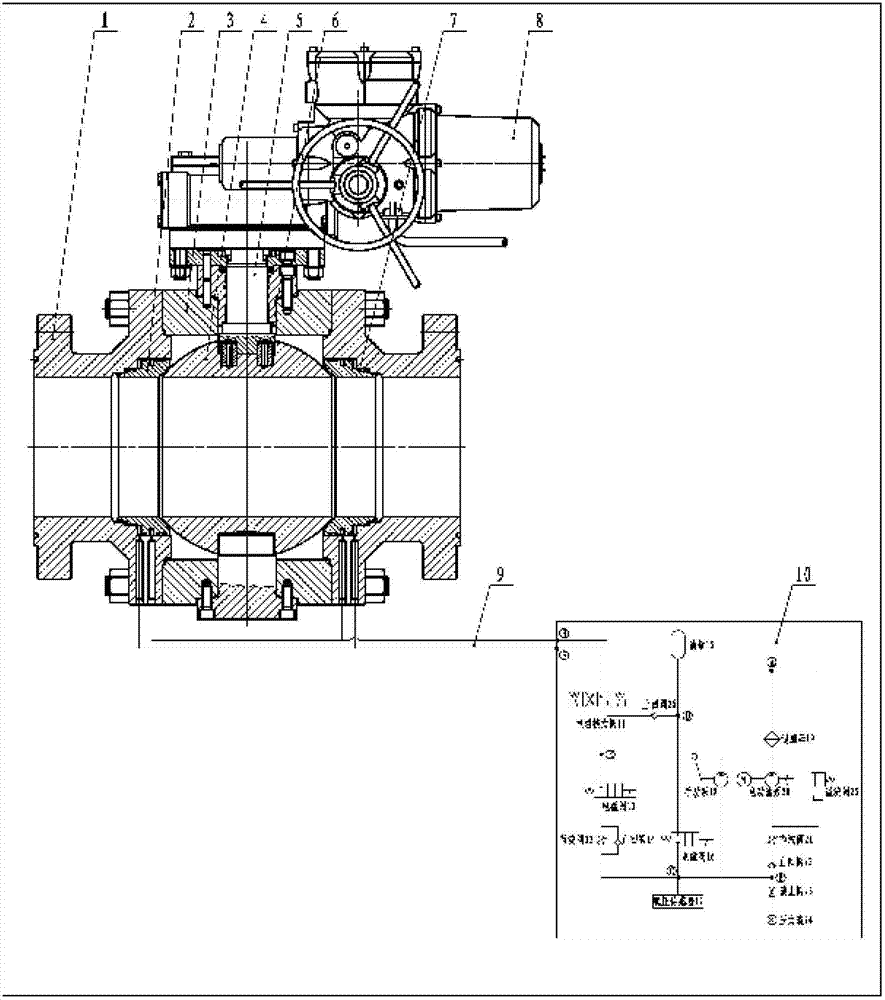
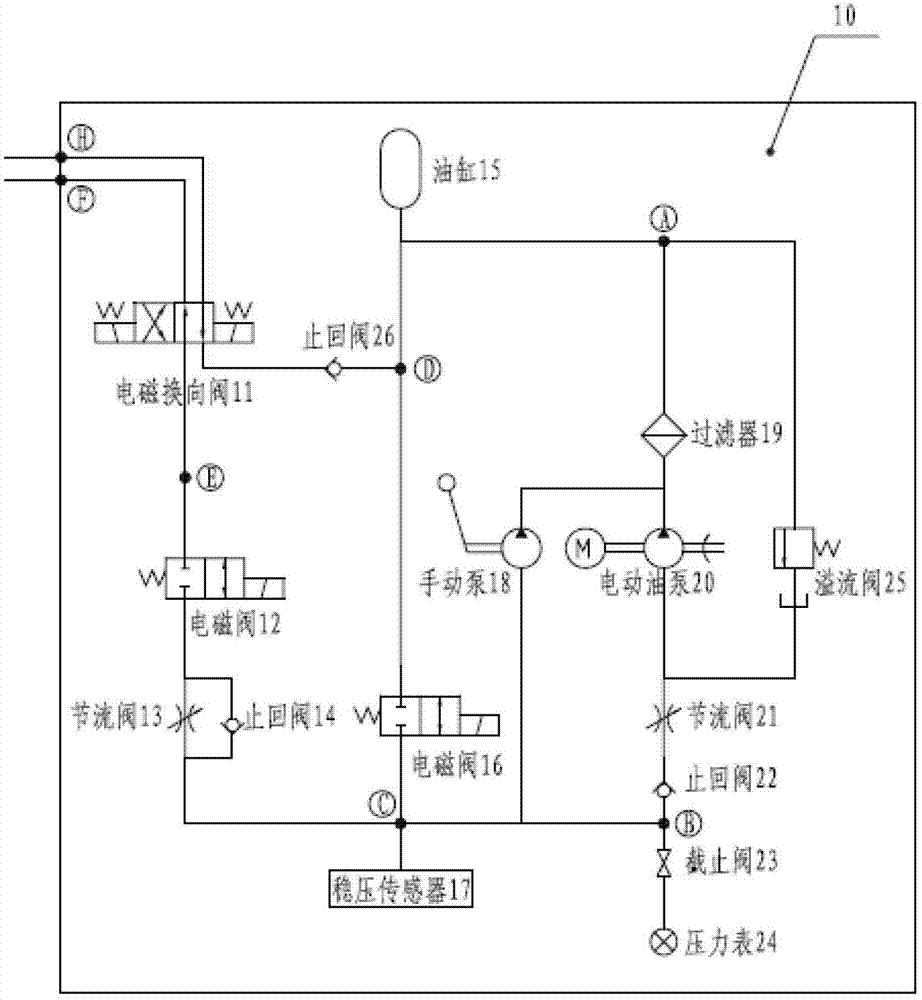
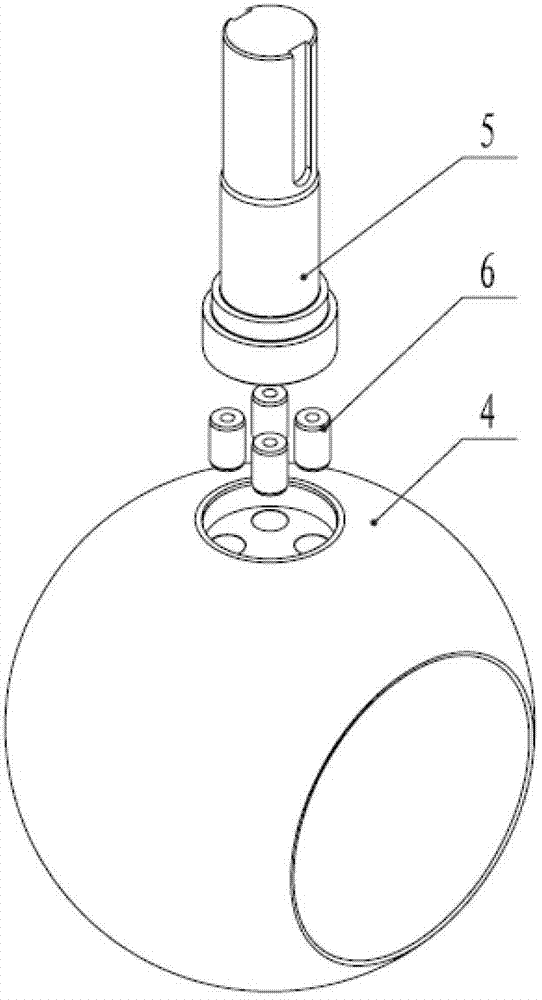
[0018] An intelligent lock valve, comprising a valve body 3, a connecting body 1, a valve seat 2, a valve core 4, a valve shaft 5 and an intelligent control cabinet 10, the valve body and the connecting bodies on both sides are installed coaxially and symmetrically, and on the valve body The valve shaft is coaxially installed, and the valve shaft is driven and rotated by the installed electric actuator 8. The valve core is coaxially fixed at the lower end of the valve shaft in the valve body, and the valve core is coaxial with the joint parts of the valve body and the connecting body. A valve seat is installed, and an O-ring 7 is installed between the valve seat and the connecting body.

[0019] The ...


PUM


Abstract

The invention relates to an intelligent locking valve, which comprises a valve body, connection bodies, valve seats, a valve core, a valve shaft and an intelligent control cabinet, wherein the valve bodies and the connection bodies on two sides are coaxially and symmetrically arranged; the valve shaft is coaxially arranged on the valve body and is driven by an electric executor to rotate; the valve core is coaxially and fixedly arranged at the lower end of the valve shaft in the valve body; the valve seats are coaxially arranged at joints of the valve cores and the valve body as well as of the valve core and the connection bodies; O-shaped sealing rings are arranged between the valve seats and the connection bodies; and the valve seats are communicated with the intelligent control cabinet through oil pipes. By the intelligent locking valve, abrasion to the sealing surface is eliminated; abrasion between the valve seats and the valve core of the conventional ball valve is avoided; when the valve seats are separated from the valve core, fluid can make 360-degree flow along a sealing surface to wash and clean impurities; the intelligent locking valve is simple in structure, scientific in design, small in switching torsion, high in sealing reliability and long in service life, has an intelligent locking function and can be widely applied to various occasions.

Description

technical field [0001] The invention belongs to valves and relates to a ball valve, in particular to an intelligent locking valve. Background technique [0002] The valves used in the working conditions of more solid granular media are very easy to wear and have a short service life during the switching process. The sealing surface is jammed by granular media and the switching torque is very large. In order to prolong the service life of the valve and be jammed by granular media, currently The best way is to set a wear-resistant hard coating on the sealing surface of the valve core and valve seat, and set a scraper to remove particles. Due to the unavoidable contact wear during the switching process, the wear resistance of the coating is limited, and the service life is short. The scraper cannot remove small particles, which leads to wear of the sealing surface of the valve core and valve seat, which reduces the sealing performance of the valve and shortens the service life....

Claims


Application Information

Patent Timeline
Patent Type & Authority Applications(China)
IPC IPC(8): F16K5/20F16K31/12
Inventor 裴耀贵閤享平潘春友赵跃文
Owner TIANJIN BAILIZHANFA GRP
Learn More