Taper thread milling cutter with internal cooling structure

A technology of thread milling cutter and cooling structure, which is applied in the direction of thread cutting tools, manufacturing tools, metal processing equipment, etc., can solve the problems of high manufacturing cost, poor processing quality, and low finish of workpieces, achieve high thread processing accuracy, and eliminate common The effect of poor performance and strong universal interchangeability

Active Publication Date: 2015-06-10
NINGBO CHUANJINGYU MECHANICAL TECH DEV
View PDF7 Cites 0 Cited by
  • Summary
  • Abstract
  • Description
  • Claims
  • Application Information

AI Technical Summary

Problems solved by technology

Not only the processing quality of taps is poor, the finish is not high, and the middle diameter is difficult to control, but also the taps are easy to wear and break during thread processing, resulting in scrapped workpieces or high manufacturing costs
When the thread milling of the tooth row is performed on the taper thread, the tool resistance is large, it is easy to vibrate, the feed cannot be increased, the tool life is short, and the tool cost is very high
Furthermore, in mechanical processing, due to the high-speed rotating cutting of milling tools, high-temperature ablation phenomenon will occur, resulting in the performance degradation or scrapping of products or tools. Therefore, in traditional milling, external coolant is used to ensure effective heat dissipation.
However, this method of externally connecting the cooling pipe also leads to too many parts at the cutting part, which makes the work very inconvenient, and the position where the coolant is sprayed is not ideal, so the effect of cooling and lubrication cannot be better achieved

Method used


Image

  • Taper thread milling cutter with internal cooling structure
  • Taper thread milling cutter with internal cooling structure
  • Taper thread milling cutter with internal cooling structure

Examples


Embodiment Construction

[0021] Embodiments of the present invention will be further described in detail below in conjunction with the accompanying drawings.

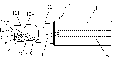
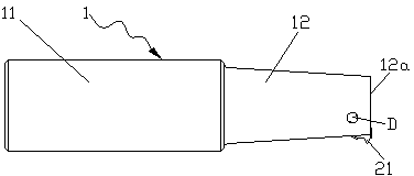
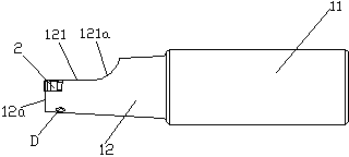
[0022] Figure 1 to Figure 6 Shown is the structural representation of the present invention.

[0023] The reference signs are: main liquid inlet channel A, directional inclined flow channel B, liquid injection port C, threaded mounting hole D, cutter body 1, cylindrical shank 11, tapered column rod 12, front end plane 12a, cut surface Platform 121 , smooth curved surface 121 a , positioning recessed area 122 , extension groove 123 , first side wall 124 , milling insert 2 , cutting edge 21 , and special screw 3 .

[0024] Such as Figure 1 to Figure 6 As shown, the tapered thread milling cutter with internal cooling structure of the present invention includes a tool holder body 1, which is composed of an integrally formed cylindrical handle 11 and a tapered column rod part 12, and the front end of the tapered column rod part 12 The milling s...


PUM


Abstract

The invention discloses a taper thread milling cutter with an internal cooling structure. The taper thread milling cutter comprises a cutter bar body, wherein the cutter bar body is composed of a cylindrical handle part and a cone-cylinder bar part which are integrally machined and shaped; a section platform advantageous for mounting and chip removal is milled at the front end of the cone-cylinder bar part; a milling blade with a triangular structure is detachably and separately assembled on the front part of the section platform; the milling blade is provided with at least one cutting edge, and only one cutting edge is located in a cutting processing position when the milling blade is assembled at any angle; an internal cooling liquid flow channel is formed in the cutter bar body; the liquid outlet of the internal cooling liquid flow channel points to the cutting processing position; and the cutter bar body is matched and combined with the milling blade to form an internally-cooled taper thread milling cutter structure. The taper thread milling cutter with the internal cooling structure has the characteristics of being simple in structure, low in cost, good in cooling effect, high in processing accuracy and long in service life, and is capable of meeting the requirements on processing of various taper threads.

Description

technical field [0001] The invention relates to the technical field of machining cutting tools, in particular to a milling tool for thread milling, in particular to a tapered thread milling cutter with an internal cooling structure. Background technique [0002] In mechanical taper thread processing, there are two main traditional processing methods: one is taper processing with taper; the other is row tooth thread milling with taper. There are certain processing defects in these traditional processing methods. The processing quality of taps is not only poor, the finish is not high, and the middle diameter is difficult to control, but also the taps are easy to wear and break during thread processing, resulting in scrapped workpieces or high manufacturing costs. In the thread milling process of tooth row, the tool resistance is large during tapered thread processing, and it is easy to vibrate, the feed cannot be increased, the tool life is short, and the tool cost is very hi...

Claims


Application Information

Patent Timeline
Patent Type & Authority Patents(China)
IPC IPC(8): B23G5/18
Inventor 袁国智任元平
Owner NINGBO CHUANJINGYU MECHANICAL TECH DEV
Why Eureka
Try Eureka