
A series topology LED switching power supply circuit

A switching power supply circuit and topology technology, applied in electrical components, regulating electrical variables, instruments, etc., to achieve the effects of easy EMI suppression, simple structure, and high operating frequency

Active Publication Date: 2016-04-20
广州泛基亚影视科技有限公司
View PDF7 Cites 0 Cited by
  • Summary
  • Abstract
  • Description
  • Claims
  • Application Information

AI Technical Summary

Problems solved by technology

[0005] The existing circuit cannot meet the above requirements in one product, especially the product electrical conversion efficiency, product cost and work reliability, etc.

Method used


Image

  • A series topology LED switching power supply circuit
  • A series topology LED switching power supply circuit
  • A series topology LED switching power supply circuit

Examples


Embodiment 1

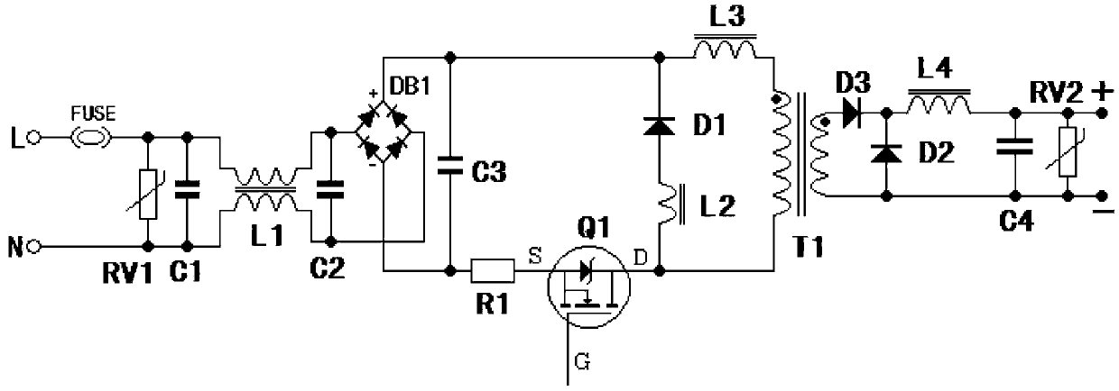
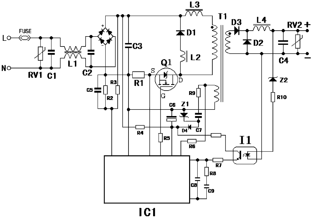
[0036] like Figure 1~3 As shown, a series topology LED switching power supply circuit includes a power supply input terminal, an input filter 1, a series topology power conversion 2, an isolated power output 3, and a power supply output terminal sequentially connected in series. Among them, L and N are the power input, RV1 is an overvoltage protection tube connected in parallel to the power input terminals L and N, the input filter 1 is composed of storage RV1, capacitor C1, common mode inductor L1, and capacitor C2, and the series topology power conversion 2 It is composed of rectifier circuit DB1, capacitor C3, energy storage inductor L3, transformer T1, inductor L2, diode D1, switch tube Q1, and resistor R1. The rectifier circuit DB1 provides directional AC output power. Capacitor C3 is connected in parallel to the directional rectifier circuit DB1. The AC zero-crossing compensation is performed on the output circuit end, the directional current output positive end of the ...

Embodiment 2

[0042] like Figure 4 As shown, the difference between this embodiment and Embodiment 1 is that this embodiment adopts the upper drive mode, a series topology LED switching power supply circuit, the circuit includes L and N as the power input, and RV1 is connected in parallel at the power input terminals L and N The overvoltage protection tube, capacitor C1, common mode inductor L1, and capacitor C2 form an input EMI filter circuit. The rectifier circuit DB1 provides directional AC output power. Capacitor C3 is connected in parallel to the directional output loop end of the rectifier circuit DB1 for AC pass Zero compensation, the directional current output positive end of the rectifier circuit DB1 is connected to the drain D end of the switch tube Q1, the source S end of Q1 is connected to the negative end of the diode D1 and one end of the inductor L3, and the other end of the inductor L3 is connected to the transformer T1 One end of the primary winding, the other end of the ...


PUM


Abstract

The invention discloses a series topological light-emitting diode (LED) switching power circuit. The circuit comprises a power input end, an input filter, a series topological electrical energy converter, an isolated electrical energy output end and a power output end, which are sequentially connected in series to form a loop. The problems of low electrical energy conversion efficiency, short service life of an LED, non-constant peak points of set output current and voltage, circuit structure complexity, large size, high product cost and the like of the prior art are solved, and the circuit has the characteristics of simple structure, high electrical energy conversion efficiency, constant current and voltage peaks, small size of a high-power density product, and the like.

Description

technical field [0001] The invention relates to LED switching power supply circuit technology, in particular to a series topology LED switching power supply circuit. Background technique [0002] LED lighting needs a switching power supply that meets a series of modern requirements, high power conversion efficiency, constant peak point of output current and voltage setting, high power density, and convenient design of topological circuits with smaller product volume and low product cost. . [0003] LEDs can be powered by a non-isolated power supply, but for safety and heat dissipation, most product applications must be powered by an isolated power supply. [0004] The requirements of LED lighting products for power supply, within the set safe working peak value, the current and voltage fluctuate softly within a certain rule range, which will prolong the working life of LED. [0005] Existing circuits cannot meet the above requirements in one product, especially the electri...

Claims


Application Information

Patent Timeline
Patent Type & Authority Patents(China)
IPC IPC(8): H02M3/315
Inventor 韩腊生韩路韩镇
Owner 广州泛基亚影视科技有限公司
Learn More