Ultrasonic heat meter
An ultrasonic and heat meter technology, used in sensor technology, flow measurement, and acoustic fields, can solve the problems of inconvenient cleaning of the inner cavity, complex structure, and damage to the reflector pressure, and achieve easy repair and maintenance, simplify the structure, and reduce signal consumption. Effect
- Summary
- Abstract
- Description
- Claims
- Application Information
AI Technical Summary
Problems solved by technology
Method used
Image
Examples
Embodiment 1
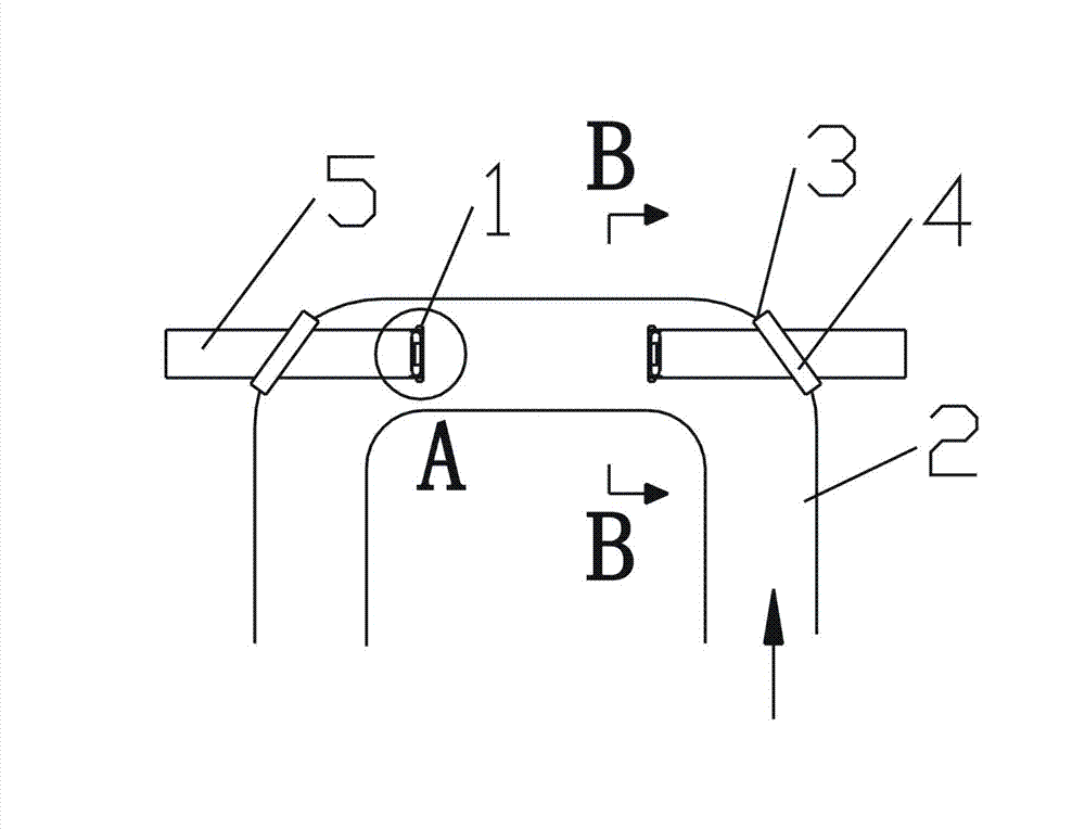
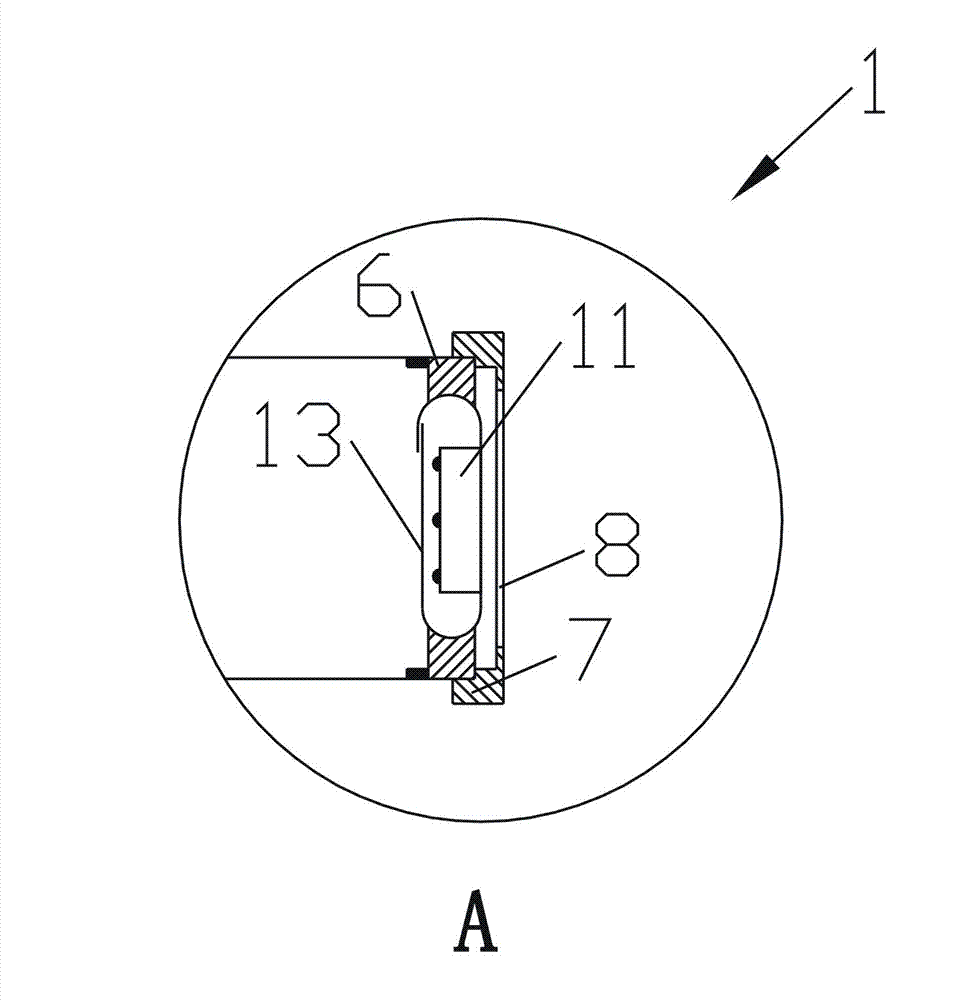
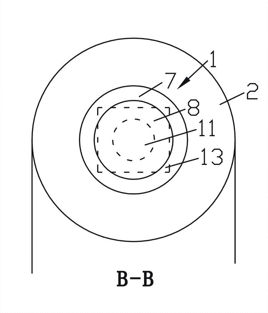
[0023] Ultrasonic heat meters, such as figure 1 As shown, it includes an ultrasonic transducer 1 and a sensor housing 2. The sensor housing 2 is U-shaped. The two ends of the sensor housing 2 are connected to the water inlet and outlet pipes. , the through hole 3 is provided with a cover 4 for sealing, the cover 4 is provided with a tube body 5 with a circular or oval radial section, one end of the tube body 5 extends into the sensor housing 2, and the tube body 5 The other end of the other end is located outside the sensor housing 2, the ultrasonic transducer 1 is arranged on the end of the tube body 5 inside the sensor housing 2, the two tube bodies 5 are in the same straight line, and the two ultrasonic transducers 1 are arranged oppositely, It can directly transmit or receive the ultrasonic signal transmitted by the other party without being reflected by the reflective surface.
[0024] The ultrasonic transducer 1 includes a piezoelectric ceramic vibrator 11, an upper pre...
Embodiment 2
[0027] Ultrasonic heat meters, such as figure 1 As shown, it includes an ultrasonic transducer 1, a sensor housing 2, and a dry pipe 9. The sensor housing 2 is U-shaped, and the two ends of the dry pipe 9 are connected to the water inlet and outlet pipes, such as Figure 4 As shown, one side of the dry pipe 9 is provided with two connecting holes 10 , the connecting holes 10 are respectively connected to two ends of the sensor housing 2 , and the dry pipe 9 and the sensor housing 2 are communicated through the connecting holes 10 . The connecting hole 10 and the sensor housing 2 can be connected by a connecting flange, so that the sensor housing 2 can be disassembled from the joint conveniently when necessary. The water flow of the main pipe 9 enters the sensor housing 2 through the connection hole 10 to form a branch flow. The connecting hole 10 is provided with a valve 14. When the sensor housing 2 needs to be disassembled, the valve 14 can be closed without cutting off the...
PUM
 Abstract
Description
Claims
Application Information
 - R&D
- Intellectual Property
- Life Sciences
- Materials
- Tech Scout
- Unparalleled Data Quality
- Higher Quality Content
- 60% Fewer Hallucinations
Browse by: Latest US Patents, China's latest patents, Technical Efficacy Thesaurus, Application Domain, Technology Topic, Popular Technical Reports.
© 2025 PatSnap. All rights reserved.Legal|Privacy policy|Modern Slavery Act Transparency Statement|Sitemap|About US| Contact US: help@patsnap.com


