Sensor with a plurality of magnet blocks adjustable in position and magnetic flux in shell
A magnetic flux and sensor technology, applied in the field of multi-point magnetic induction to provide control signals, can solve the problems of unstable motor operation, no control signal, different and other problems
- Summary
- Abstract
- Description
- Claims
- Application Information
AI Technical Summary
Problems solved by technology
Method used
Image
Examples
Embodiment 1
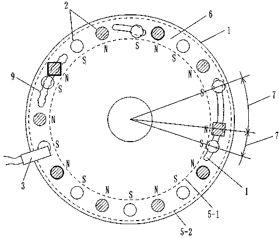
[0128] Embodiment 1, a sensor with adjustable positions and magnetic fluxes of multiple magnetic blocks in the housing
[0129] like figure 1 , 3 , 4. The sensor in this embodiment includes a sensing element connected in sequence, a booster model processor 21, a digital-to-analog converter 27 and an operational amplifier 28;
[0130] [1] The sensing element is an element that converts the rotational motion of the annular groove rotating disk 1 into a rectangular wave signal output;
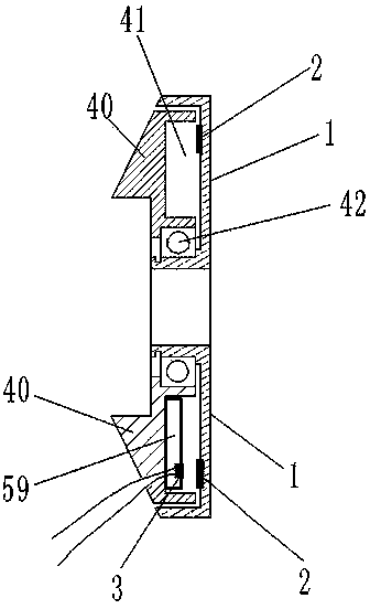
[0131] The concave surfaces of an annular groove rotating disk 1 and an annular groove fixing disk 40 are opposite, and the size of the annular groove rotating disk 1 and the annular groove fixing disk 40 is just enough to make the annular groove fixing disk 40 fit in the ring. In the annular groove of the groove rotating disk 1, two disks are synthesized into a fitting inner hollow shell that can rotate relatively, and the concave surfaces of the two disks are sandwiched into a hollow ring 41;...
Embodiment 2
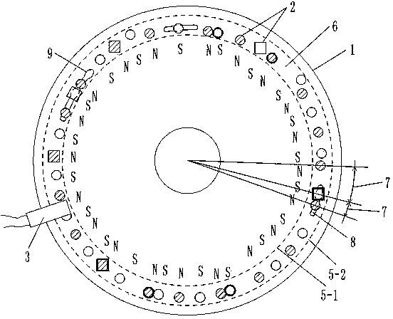
[0150] Embodiment 2, high-density multi-magnetic block position and adjustable magnetic flux sensor in the housing
[0151] like figure 2 , 3 , 4, the annular groove rotating disk 1 surface diameter in the hollow ring 41 is 10.0 centimeters, establishes 40 permanent magnet pieces 2 in the annular groove rotating disk 1, and the diameter of 40 permanent magnet pieces 2 is respectively 0.6 centimetre, and the magnetic flux is 146---279(B·H)max / KJ·m -3 Different selection values within the range, and the magnetic flux of adjacent permanent magnet block 2 is not equal. Hall 3 keeps a distance of 0.2 cm from each permanent magnet 2 in the rotating state, so that when each rotating permanent magnet 2 passes through Hall 3, Hall 3 can generate a corresponding rectangular wave electric signal output. The circle where the arc of the arc-shaped bar-shaped short groove 8 is located and the inner circular locus 5-1 are concentric circles. The structures of other rotating disk 1, pe...
Embodiment 3
[0152] Embodiment 3, a sensor with adjustable positions and magnetic fluxes of multiple magnetic blocks in the casing with a specific circuit
[0153] like figure 1 , 3 , 5. The sensor in this embodiment includes a sensing element connected in sequence, a booster model processor 21, a digital-to-analog converter 27 and an operational amplifier 28;
[0154] [1] The Hall 3 in the sensing element is UGN3075; the structure of other elements and elements in the sensing element is the same as that in Embodiment 1;
[0155] [2] The auxiliary model processor 21 selects the single-chip microcomputer 31 to complete all functions, and the single-chip microcomputer 31 selects AT89S52. That is, the AT89S52 single-chip microcomputer 31 completes all functions of the analog-to-digital conversion and the wave width peak recognizer 22 , the power-assisted starting point selector 23 , the magnet speed calculator 24 , the power-assisted model memory 25 and the power-assisted model calculator ...
PUM
 Abstract
Description
Claims
Application Information
 - R&D
- Intellectual Property
- Life Sciences
- Materials
- Tech Scout
- Unparalleled Data Quality
- Higher Quality Content
- 60% Fewer Hallucinations
Browse by: Latest US Patents, China's latest patents, Technical Efficacy Thesaurus, Application Domain, Technology Topic, Popular Technical Reports.
© 2025 PatSnap. All rights reserved.Legal|Privacy policy|Modern Slavery Act Transparency Statement|Sitemap|About US| Contact US: help@patsnap.com


