Water heating machine capable of rapidly providing boiling water
A technology of boiling water machine and boiling water, which is applied in the direction of water boiling appliances, etc., which can solve the problems of frequent start and stop, imperfect practicality, and noise of the pump, etc., and achieve the effect of convenient use, simple structure, and zero watts of standby power consumption
- Summary
- Abstract
- Description
- Claims
- Application Information
AI Technical Summary
Problems solved by technology
Method used
Image
Examples
Embodiment 1
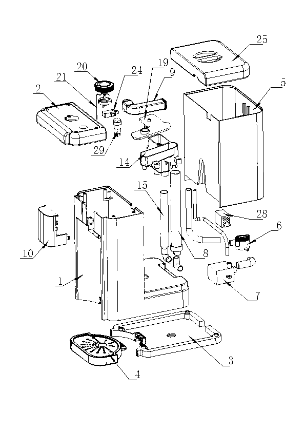
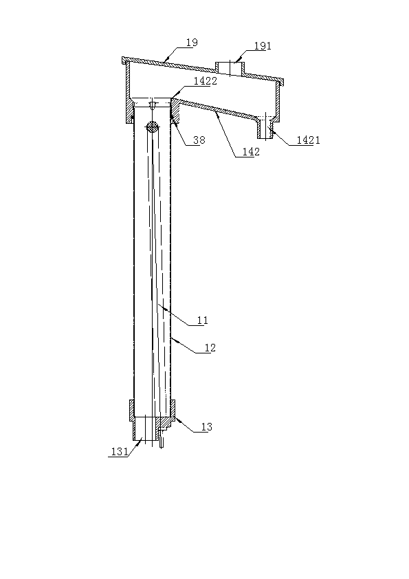
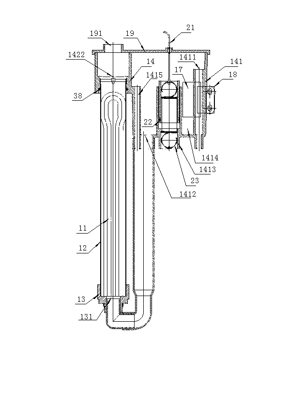
[0024] The water boiler consists of a housing 1, a panel 2, a bottom plate 3, a water tray 4, a water tank 5, an outer water tank socket 6, a water pump 7, a heater assembly 8, an exhaust pipe 9, a water outlet cover 10, a water tank cover 25, Pipeline, control circuit and water temperature adjustment system, such as figure 1 , the housing 1 is in an "L" shape, the water tank 5 is arranged on the rear side of the housing 1, forming a cuboid, the outer water tank socket 6 is arranged at the bottom of the water tank 5, the water pump 7 is arranged at the lower part inside the housing 1, and the heater assembly 8 is the core of the water boiler, which is arranged in the center of the housing 1. One end of the exhaust pipe 9 is connected to the exhaust hole 191 of the heater assembly 8, and the other end is connected to the upper part of the water tank 5. When the water boiler is working, the water will be boiled. Boiling will cause pressure fluctuations in the water outlet cavity...
Embodiment 2
[0031] The steam exhaust pipe 9 of the water boiler can also be communicated with the steam exhaust nozzle 37, and the steam exhaust nozzle 37 is integrated with the water outlet nozzle 36, as Figure 7 .
Embodiment 3
[0033] Described water boiler, its control circuit also can be by power cord 26, fuse 27, main control board 33, button display board 34, reed switch 18, thermal protector 31, thermal fuse 32, temperature sensor 35, water pump 7, The micro switch 24 and the electric heating tube 11 are composed, and the circuit diagram is as follows: Image 6 , in this solution, the button display panel 34, the water temperature adjustment knob 20 and the micro switch 24 are installed on the panel 2, and the temperature sensor 35 is installed in the water outlet chamber 142.
PUM
 Abstract
Description
Claims
Application Information
 - R&D Engineer
- R&D Manager
- IP Professional
- Industry Leading Data Capabilities
- Powerful AI technology
- Patent DNA Extraction
Browse by: Latest US Patents, China's latest patents, Technical Efficacy Thesaurus, Application Domain, Technology Topic, Popular Technical Reports.
© 2024 PatSnap. All rights reserved.Legal|Privacy policy|Modern Slavery Act Transparency Statement|Sitemap|About US| Contact US: help@patsnap.com


