
Combustion appliance for raising the temperature of exhaust gas

A burner and exhaust gas technology, which is applied in the direction of burner, combustion method, combustion type, etc., can solve the problems of exhaust gas flow change, burner flameout, incomplete combustion, etc., to improve combustibility, improve combustibility, prevent flameout or incomplete burn effect

Inactive Publication Date: 2012-11-14
HINO MOTORS LTD
View PDF7 Cites 6 Cited by
  • Summary
  • Abstract
  • Description
  • Claims
  • Application Information

AI Technical Summary

Problems solved by technology

[0008] However, when the exhaust gas heating burner is installed in the exhaust system of the vehicle, the running state of the vehicle changes greatly due to repeated acceleration and deceleration, and the flow rate of the exhaust gas also fluctuates greatly. possibility of incomplete combustion

Method used


Image

  • Combustion appliance for raising the temperature of exhaust gas
  • Combustion appliance for raising the temperature of exhaust gas
  • Combustion appliance for raising the temperature of exhaust gas

Examples


Embodiment Construction

[0035] Embodiments of the present invention will be described below with reference to the drawings.

[0036] figure 1 represents an embodiment of the present invention, figure 1 Reference numeral 1 in the figure indicates an exhaust pipe 2 that guides the exhaust gas 1 after passing through the turbine of a turbocharger (not shown), and the curved portion of the exhaust pipe 2 that is bent into an L shape is equipped with a nozzle that can pass through the exhaust pipe 2. A burner 3 for raising the temperature of the exhaust gas 1 is obtained by combusting a flame.

[0037]Here, the bent portion of the exhaust pipe 2 is constituted by a casing 4 disposed approximately at right angles to the exhaust pipe 2 from the upstream side and directed toward the downstream side in the flow direction of the exhaust gas 1 . The filter 3 is accommodated in the casing 4, and the particulate filter 6 held by the other casing 5 is interposed between the casing 4 and the exhaust pipe 2 on the...


PUM


Abstract

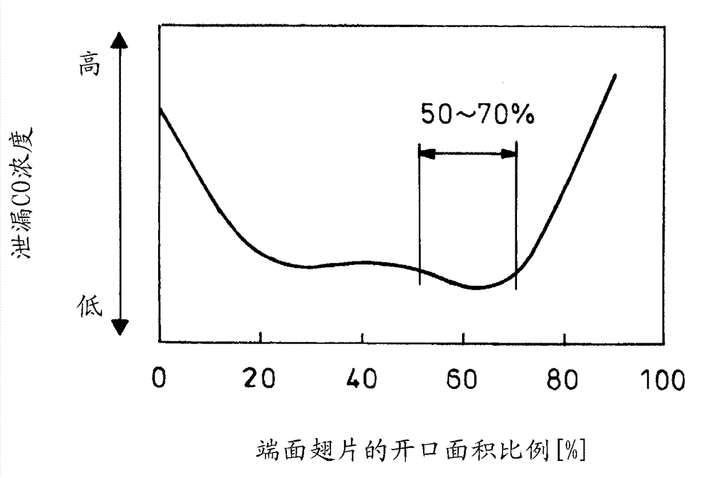
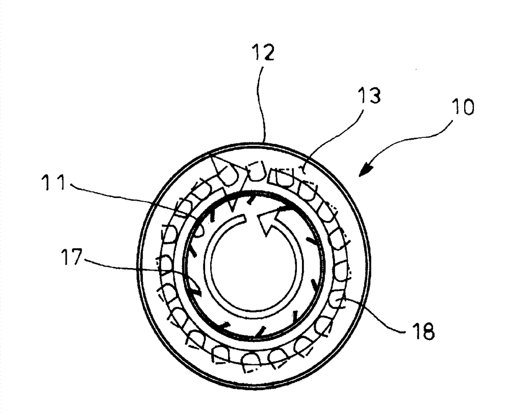
Disclosed is a combustion appliance for raising the temperature of exhaust gas comprised of a fuel injection nozzle (7), electrode rods (ignition devices) (8, 9) and a double cylinder type flame stabiliser (10) disposed so as to encompass the surrounding area thereof; closed on the distal side by a torus-shaped blocking plate (13) disposed between an inner cylinder (11) and an outer cylinder (12) of the flame stabiliser, and connected to one end of a combustion air guide line (15) which guides combustion air (14) between the inner cylinder (11) and outer cylinder (12); with a plurality of combustion air flow holes (16) disposed at the proximal end of the outer cylinder (11), and a plurality of peripheral fins (17) at a different position farther towards the distal end of the circumference of the inner cylinder (11) therefrom which are formed by cutting and raising radially inwards so as to guide the combustion air (14) from a circumferential direction and provide a swirling flow inside the inner cylinder (11); and a plurality of end face fins (18) also formed on the blocking plate (13) by cutting and raising in the direction of fuel injection so as to discharge the combustion air (14) in a circumferential direction and provide a swirling flow around the flame (21).

Description

technical field [0001] The invention relates to a burner for raising the temperature of exhaust gas. Background technique [0002] Conventionally, diesel engines have been equipped with a particulate filter in the middle of the exhaust pipe through which the exhaust gas flows, and the particulate matter (Particulate Matter: particulate matter) contained in the exhaust gas is collected by the particulate filter. Oxidation catalysts with Pt or Pd as active species are carried, so that the collected particles start self-combustion from a very low exhaust temperature. [0003] However, since the collection amount is greater than the processing amount of particulates in the operating region where the exhaust temperature is low, when the operating state at such a low exhaust temperature continues, regeneration of the particulate filter cannot be performed well and the particulate filter The possibility of the device getting stuck in an overcollection state. [0004] Therefore, c...

Claims


Application Information

Patent Timeline
Patent Type & Authority Applications(China)
IPC IPC(8): F23D11/24F01N3/02F23G7/06
CPCF01N3/0256F01N2470/18F01N2240/14F01N2240/20F23D2900/21003F23G7/065F01N3/025F23D2900/21006
Inventor 津曲一郎涩谷亮高安正纯
Owner HINO MOTORS LTD
Learn More