Power transmission device
A technology of power transmission device and rolling parts, applied in the direction of transmission device, friction transmission device, belt/chain/gear, etc., can solve the problems such as the inability to eliminate the spin torque and the reduction of torque transmission efficiency.
- Summary
- Abstract
- Description
- Claims
- Application Information
AI Technical Summary
Problems solved by technology
Method used
Image

Examples
Embodiment 1
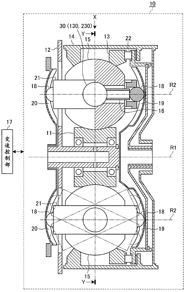
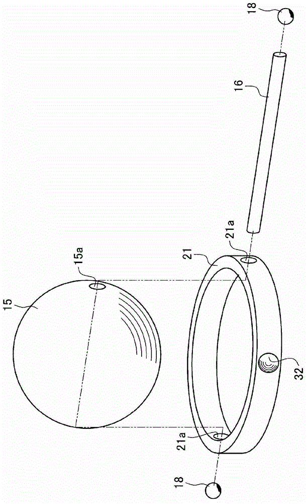
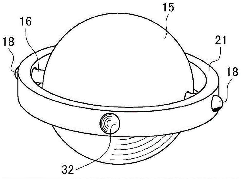
[0022] based on Figure 1 to Figure 6 Embodiment 1 of the power transmission device according to the present invention will be described. Here, as the power transmission device, a continuously variable transmission will be described as an example.
[0023] First, use figure 1 An example of the continuously variable transmission of the first embodiment will be described. figure 1 The reference numeral 10 in the figure shows the continuously variable transmission of the present embodiment 1. This continuously variable transmission 10 has a continuously variable transmission mechanism constituting a transmission unit.
[0024] This continuously variable transmission mechanism is a so-called traction planetary gear mechanism, and includes first to fourth rotation elements 11 to 14 that can rotate relative to each other, and the first to fourth rotation elements 11 to 14 have a common rotation center axis. R1; and a plurality of fifth rotation elements 15 having a rotation cent...
Embodiment 2
[0056] based on Figure 7 Embodiment 2 of the power transmission device according to the present invention will be described. In this second embodiment as well, a continuously variable transmission will be described as an example of the power transmission device.
[0057] The continuously variable transmission 10 of the second embodiment is obtained by changing the rotation suppressing portion 30 of the first embodiment into another form.
[0058] For example, the rotation suppressing portion 30 of the first embodiment requires a new member called a convex curved body 31 compared to the conventional continuously variable transmission having the annular member 21 , which may lead to an increase in cost. Therefore, in the continuously variable transmission 10 of the second embodiment, in order to suppress an increase in cost, it is replaced with Figure 7 The rotation inhibiting portion 130 is shown.
[0059] The rotation suppressing portion 130 includes: a convexly curved su...
Embodiment 3
[0069] based on Figure 8 Embodiment 3 of the power transmission device according to the present invention will be described. Embodiment 3 is also described by taking a continuously variable transmission as an example of a power transmission device.
[0070] The continuously variable transmission 10 of the third embodiment is obtained by changing the rotation suppressing part 30 of the first embodiment or the rotation suppressing part 30 of the second embodiment to another form.
PUM
 Abstract
Description
Claims
Application Information
 - R&D
- Intellectual Property
- Life Sciences
- Materials
- Tech Scout
- Unparalleled Data Quality
- Higher Quality Content
- 60% Fewer Hallucinations
Browse by: Latest US Patents, China's latest patents, Technical Efficacy Thesaurus, Application Domain, Technology Topic, Popular Technical Reports.
© 2025 PatSnap. All rights reserved.Legal|Privacy policy|Modern Slavery Act Transparency Statement|Sitemap|About US| Contact US: help@patsnap.com