
Mobile phase degassing processing device in simulated moving bed separation technology

A technology of simulating moving bed and separation technology, which is applied in the field of mobile phase degassing treatment devices, can solve the problems of changing the running route of the material and liquid, affecting the separation effect of the system, reducing the service life of the resin, etc. The effect of flashing area and prolonging service life

Inactive Publication Date: 2012-11-14
山东兆光色谱分离技术有限公司 +1
View PDF6 Cites 1 Cited by
  • Summary
  • Abstract
  • Description
  • Claims
  • Application Information

AI Technical Summary

Problems solved by technology

[0002] In the simulated moving bed chromatographic separation system, the mobile phase often forms a gas-containing liquid due to dissolved oxygen or mixed with air. After entering the system, it will gradually accumulate to form large bubbles. These bubbles will change the route of the liquid in the resin medium. , thus affecting the separation effect of the system
On the other hand, when the system is running at high temperature, the oxygen in the solution dissociates at high temperature to produce strong oxidation, which causes the aging of the resin, which is prone to resin breakage and reduces the service life of the resin.
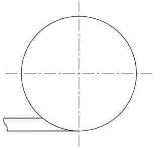
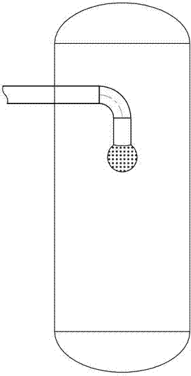
The traditional deoxidation device is either tangentially fed for deoxidation, such as Figure 4 , but the deoxidation effect is not good; or spray atomization flash deoxidation, such as Figure 5 , this way will increase power consumption

Method used


Image

  • Mobile phase degassing processing device in simulated moving bed separation technology
  • Mobile phase degassing processing device in simulated moving bed separation technology
  • Mobile phase degassing processing device in simulated moving bed separation technology

Examples


Embodiment Construction

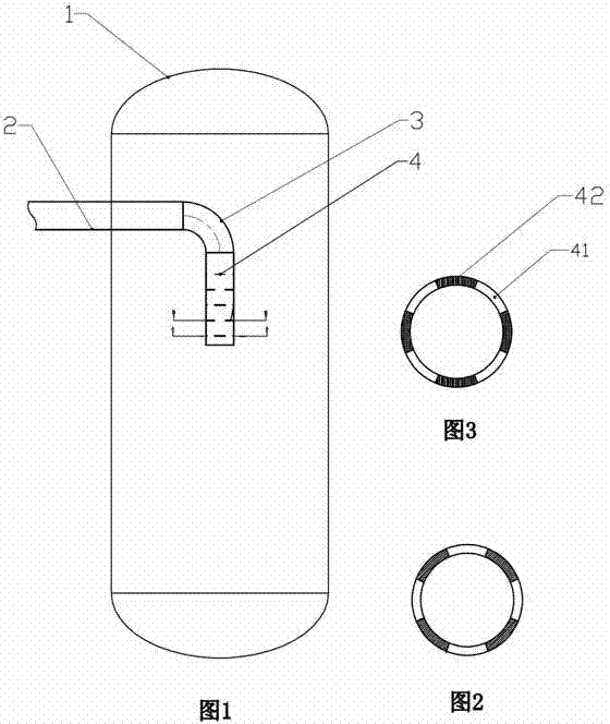
[0016] Such as figure 1 , figure 2 , image 3 . The mobile phase degassing treatment device in the simulated moving bed separation technology includes a flash tank 1, and the feed pipe 2 is connected to the nozzle located in the upper center of the flash tank 1 through an elbow 3. The nozzle is a columnar multi-layer film Nozzle 4, the feed liquid is sprayed on the inner wall of the container of the flash degassing device in the form of a film. The laminar nozzle 4 is provided with laminar slits 41 distributed in the horizontal direction along the cylindrical surface, and the adjacent laminar slits 41 in the up and down direction are dislocated, and the adjacent laminar slits 41 are formed by the laminar nozzle walls 42 .

[0017] There are four film slits 41 distributed along the circumference of the cylinder, and the slits of each film are of the same size, and the distance between adjacent film slits in the horizontal direction is equal to the circumferential length o...


PUM


Abstract

The invention discloses a mobile phase degassing processing device in a simulated moving bed separation technology, belonging to the field of chemical engineering equipment. The mobile phase degassing processing device comprises a flash evaporation tank, wherein a feed pipe is connected with a spray nozzle positioned in the center position of the upper part of the flash evaporation tank through an elbow, and the mobile phase degassing processing device is characterized in that the spray nozzle is of a cylindrical multi-layer film spray nozzle, layer film gaps in the horizontal direction are distributed in the circumferential direction of the cylindrical layer film spray nozzle along the cylindrical surface, and the adjacent layer film gaps in the up-and-down direction are in dislocation. As a feed liquid is sprayed like a thin film, the flash evaporation area is increased, and the flash evaporation effect is increased; and a secondary flash evaporation effect can be formed after the feed liquid is sprayed on the inner wall of a container, and the flash evaporation effect is increased. The device is designed into dislocation flash evaporation and can prevent the thin film of the feed liquid from mixing, and simultaneously produce the good flash evaporation effect. The mobile phase degassing processing device disclosed by the invention can greatly reduce the content of dissolved oxygen, better protect resin from being oxidized and prolong the service life.

Description

technical field [0001] The invention relates to a simulated moving bed separation technology, in particular to a mobile phase degassing treatment device in the simulated moving bed separation technology. Background technique [0002] In the simulated moving bed chromatographic separation system, the mobile phase often forms a gas-containing liquid due to dissolved oxygen or mixed with air. After entering the system, it will gradually accumulate to form large bubbles. These bubbles will change the route of the liquid in the resin medium. , thus affecting the separation effect of the system. On the other hand, during the high-temperature operation of the system, the oxygen in the solution dissociates at high temperature to produce strong oxidation, which causes the aging of the resin, which is prone to resin breakage and reduces the service life of the resin. The traditional deoxidation device is either tangentially fed for deoxidation, such as Figure 4 , but the deoxidation...

Claims


Application Information

Patent Timeline
IPC IPC(8): B01D19/00B01D3/06B01D15/18
Inventor 王兆光
Owner 山东兆光色谱分离技术有限公司
Learn More