Electric valve

An electric valve and valve seat technology, applied in valve details, valve device, valve shell structure, etc., can solve the problems of strength reduction, top 1012 fatigue failure, and electric valve top 1012 failure strength reduction, etc., to improve the resistance to fatigue and impact failure. ability to ensure the effect of anti-destructive ability

Inactive Publication Date: 2012-11-07
ZHEJIANG SANHUA CO LTD
View PDF7 Cites 9 Cited by
  • Summary
  • Abstract
  • Description
  • Claims
  • Application Information

AI Technical Summary

Problems solved by technology

[0007] In the electric valve with this structure, the thickness of the top 1012 of the housing 101 is basically the same as that of the peripheral wall 1011. After the top 1012 is welded to the mandrel 102, the material of the top 1012 will be affected by the welding heat, and the strength will decrease to a certain extent. When in use, the destructive strength of the top 1012 of the electric valve will be significantly reduced; moreover, the top 1012 of the housing 101 is basically in a flat top state, and its thickness is basically the same as that of the peripheral wall 1011. When the mandrel 102 is impacted by the rotor, the housing The top of the 1012 is prone to fatigue failure

Method used


Image

  • Electric valve
  • Electric valve
  • Electric valve

Examples


Embodiment Construction

[0032] The purpose of the present invention is to provide an electric valve, the casing of which has high strength and the ability to resist fatigue failure.

[0033] In order to enable those skilled in the art to better understand the technical solutions of the present invention, the present invention will be further described in detail below in conjunction with the accompanying drawings and specific embodiments.

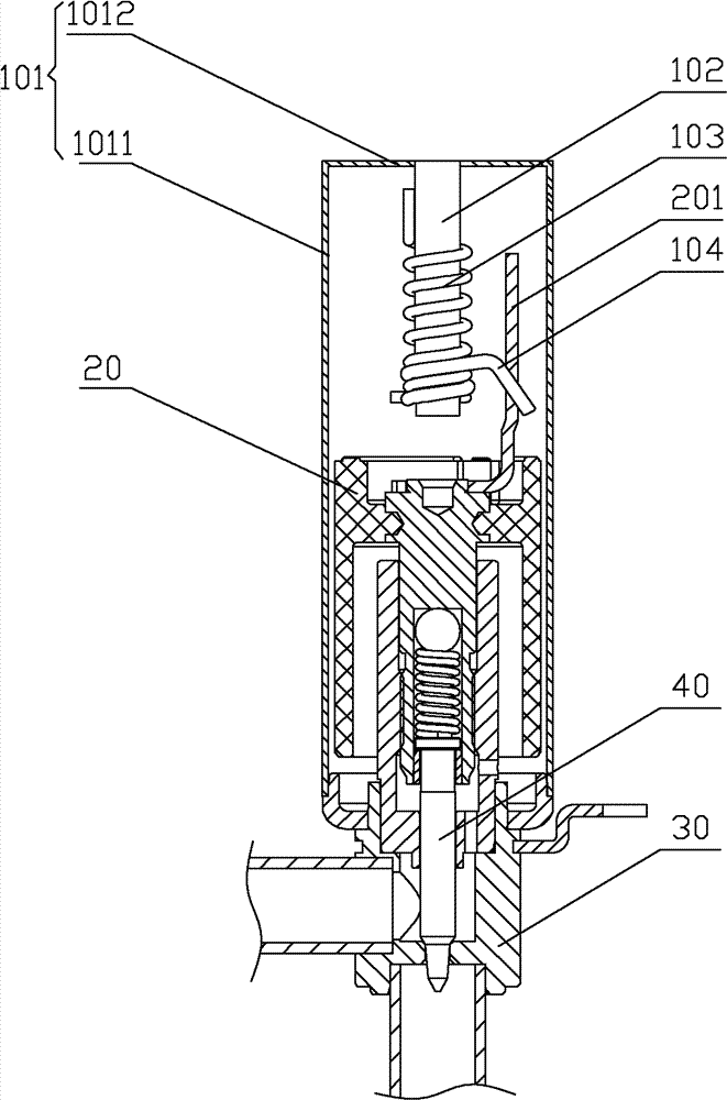
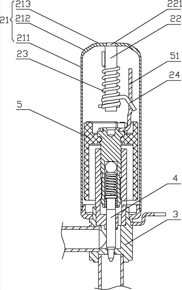
[0034] Please refer to figure 2 , figure 2 It is a structural schematic diagram of the first specific embodiment of the electric valve provided by the present invention; image 3 for figure 2 Schematic diagram of the disassembly of the middle casing, in which the casing is partially cut; Figure 4 for figure 2 An enlarged cross-sectional view of the top of the middle shell after welding to the mandrel.

[0035] The electric valve provided by this embodiment has a casing, a valve seat 3 and a rotor device 5, a valve needle part 4 is arranged in the valve ch...


PUM


Abstract

The invention discloses an electric valve which comprises a casing, a valve seat (3) and a rotor device (5), wherein the casing comprises a casing body (21) and a mandrel (22) fixedly welded with the top (213) of the casing body (21). The casing body (21) is an integrated casing body formed by stamping and drawing, and the thickness delta 1 of the top (213) is larger than the thickness delta 2 of a periphery (211) of the casing body (21). Since the thickness of the top of the casing body is larger than that of the periphery, weakening of material strength of the top and the mandrel caused by welding heat influences can be offset, breaking strength of the top of the casing body of the electric valve can be guaranteed to be consistent with that of the periphery, and breaking resistance of the whole casing body is guaranteed. Besides, the thickness of the top of the casing body is increased, so that impact fatigue failure resistance of the joint of the casing body and the mandrel can be improved.

Description

technical field [0001] The invention relates to the field of flow regulating valves, in particular to an electric valve. Background technique [0002] Flow regulating valves are usually used in air conditioners, refrigerators, heat pumps, water heaters, various refrigeration and heating equipment, or other occasions where fluid flow needs to be adjusted, and electric valves are one type of flow regulating valves. [0003] Please refer to figure 1 , figure 1 It is a schematic diagram of the structure of a typical electric valve. [0004] The electric valve has a casing, a valve seat 30 and a rotor device 20, and a valve needle part 40 is arranged in the valve chamber of the electric valve. The rotor device 20 drives the magnetic rotor and the screw rod connected to it through the coil, and the screw rod drives the valve needle part 40 to move axially through the thread structure, so that the valve needle controls the opening of the valve port, thereby controlling the flow ...

Claims


Application Information

Patent Timeline
IPC IPC(8): F16K31/04F16K27/00
Inventor 不公告发明人
Owner ZHEJIANG SANHUA CO LTD
Why Eureka
Try Eureka