Gate system for hydropower station
A technology for hydropower stations and gates, which is applied in the field of gate systems, can solve problems such as dam overturning accidents, unsecured power supply for plants, and unsteady force on gates, etc., to reduce the steel materials used for supports, improve lifting efficiency, and support forces on supports Reduced effect
- Summary
- Abstract
- Description
- Claims
- Application Information
AI Technical Summary
Problems solved by technology
Method used
Image
Examples
Embodiment 1
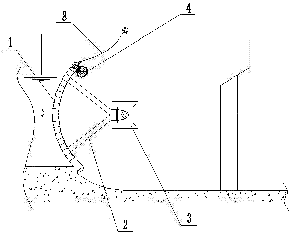
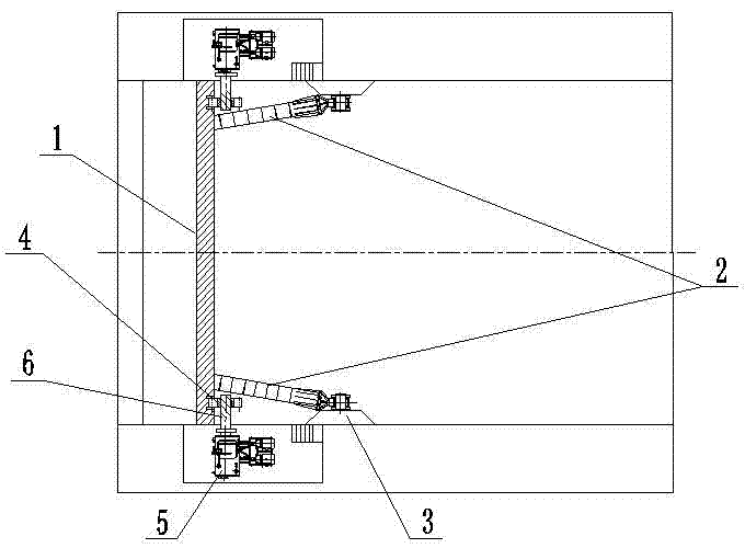
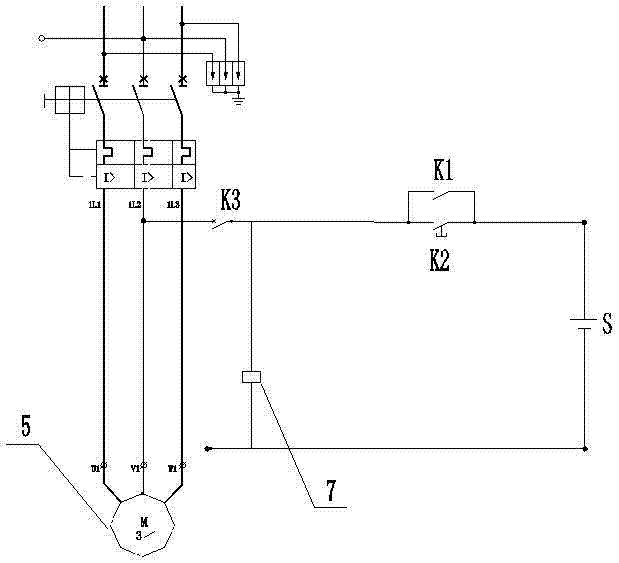
[0029] Such as figure 1 , figure 2 and image 3 As shown, the present embodiment includes arc-shaped gate 1, transmission device and control circuit. Gate 1 is movable and fixed on supports 3 on both sides of the dam through pull rod 2. With support 3 as the center, gate 1 can be vertically Make circular motion in the plane; the transmission device includes transmission gear 4 and frequency conversion motor 5, transmission gear 4 and frequency conversion motor 5 are linked, and transmission gear 4 cooperates with the rack of gate 1 to realize the opening and closing of gate 1 under normal working conditions .
[0030] The rotating shaft 6 of the transmission gear 4 of this embodiment is provided with a brake device 7, and the brake device 7 is connected in series in the circuit where the variable frequency motor 5 is located. The working principle of the brake device 7 is similar to that of an elevator brake. When charged, the brake device 7 is charged and opened, and the ...
Embodiment 2
[0036] Compared with Embodiment 1, this embodiment increases the control of the frequency conversion motor. In order to make the gate 1 move more smoothly, two racks are provided on the gate 1, and a transmission device is provided on each side of the gate 1. , the gate 1 is opened and closed by driving the transmission devices on both sides. Since the speeds of the variable frequency motors 5 on both sides cannot be 100% consistent, it is necessary to calculate the deviation on both sides of the gate 1 through PLC, and then send commands to the two variable frequency motors 5. Control the rotational speed of the variable frequency motor 5 to eliminate the deviation on both sides of the gate 1 .
[0037] In order to better realize the present invention, an angular displacement sensor is installed on the left and right sides of the gate 1, and then the angular displacement information on the left and right sides of the gate 1 is converted into opening information through an enco...
Embodiment 3
[0039] This embodiment is basically the same as Embodiment 1, the difference is that the cross-sectional shape of the gate 1 is designed to be 1 / 4 circle, and the gate 1 is in a fully closed state such as Figure 4 As shown, the opening of gate 1 under normal conditions is that gate 1 is opened by Figure 4 The position moves clockwise to Image 6 The position shown; and the opening of the gate 1 in an emergency situation is, by Figure 4 The position shown moves counterclockwise to Figure 5 In the position shown, the power in the emergency opening process comes from the gravity of the gate 1 itself. The traditional gate 1 can only be opened by external power in an emergency situation, and when the power is missing, the gate 1 cannot be opened in time, which will bring serious consequences. However, the gate 1 of this embodiment does not need external power when it is opened in an emergency. solved the problem.
PUM
 Abstract
Description
Claims
Application Information
 - R&D
- Intellectual Property
- Life Sciences
- Materials
- Tech Scout
- Unparalleled Data Quality
- Higher Quality Content
- 60% Fewer Hallucinations
Browse by: Latest US Patents, China's latest patents, Technical Efficacy Thesaurus, Application Domain, Technology Topic, Popular Technical Reports.
© 2025 PatSnap. All rights reserved.Legal|Privacy policy|Modern Slavery Act Transparency Statement|Sitemap|About US| Contact US: help@patsnap.com


