Continuous casting billet strengthening device and strengthening method in continuous casting process

A strengthening device and continuous casting slab technology, which is applied in the field of metallurgical continuous casting, can solve problems such as huge equipment, difficulty in popularization, and inappropriate control

Inactive Publication Date: 2012-11-07
LAIWU IRON & STEEL GRP
View PDF5 Cites 4 Cited by
  • Summary
  • Abstract
  • Description
  • Claims
  • Application Information

AI Technical Summary

Problems solved by technology

[0004] Although electromagnetic stirring has achieved certain effects on grain refinement and central segregation reduction, there are still some problems: (1) Electromagnetic stirring in continuous casting production consumes most of the power supply energy in the gap between the coil and the molten steel Eddy current losses in the gap or conductor material, i.e. heating
Improper control in any aspect will not only fail to improve the center segregation, but also easily cause cracks in the center of the slab, making it difficult to apply accurately
In addition, the main disadvantages of heavy pressure and continuous forging are that the equipment is huge, the investment and cost are high, so it is difficult to promote
The strong cooling method under thermal stress micro-reduction is limited by the cross-sectional size of the slab, which will also bring some negative effects, such as increasing the incidence of cracks in the slab and reducing the straightening temperature.

Method used


Image

  • Continuous casting billet strengthening device and strengthening method in continuous casting process

Examples


Embodiment 1

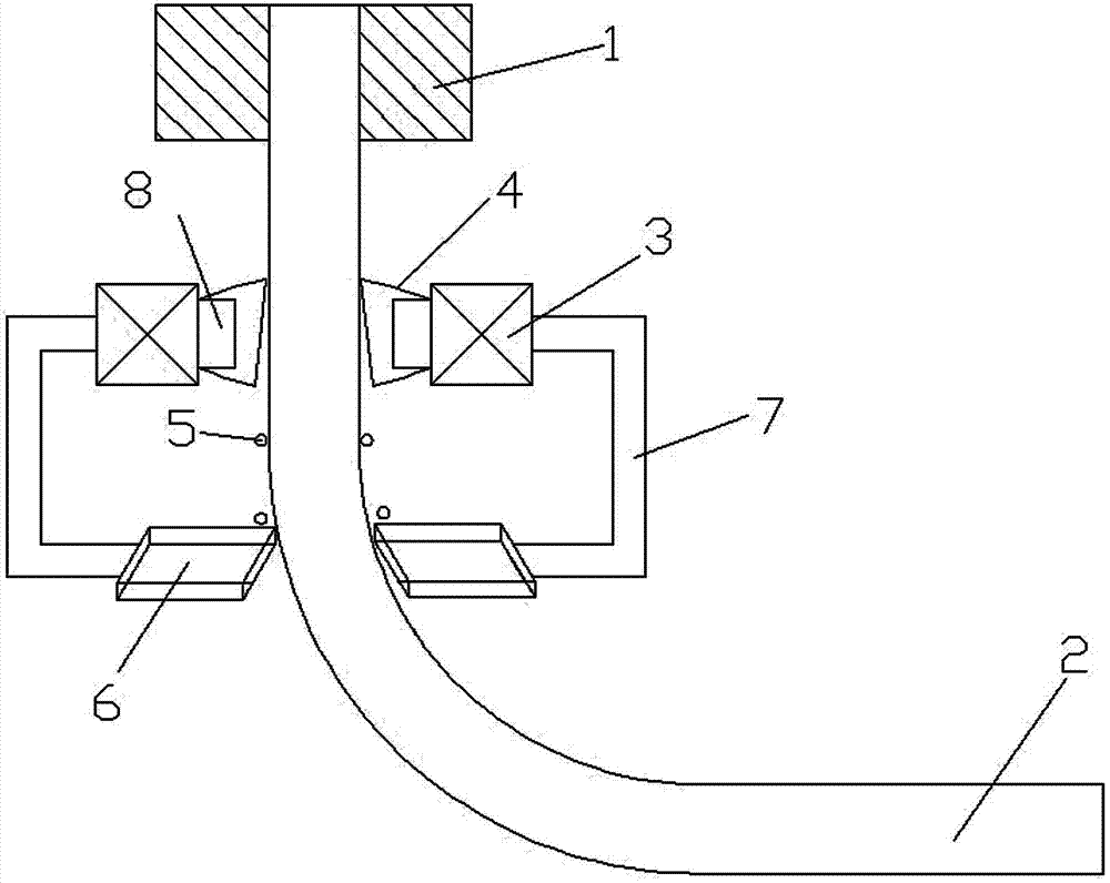
[0031] Embodiment 1: The continuous casting slab 2 with a certain thickness on the surface is formed after the molten steel passes through the vibrating crystallizer 1 . The shot blaster 3 after the fixed position can throw the steel shot 5 according to a certain speed range, and the steel shot 5 hits the surface of the continuous casting slab 2 through the shot blasting channel 7 . Protective cover 4 can be beneficial to the collection of steel shot 5 and safe production. The steel shot 5 enters the steel shot collection box 6 after being collected, and enters the shot blaster 3 through the shot pipeline 7 . The continuous casting slab 2 treated by the strengthening device of the continuous casting slab in the above continuous casting process can offset part of the thermal stress, reduce the number and length of cracks, and reduce the tendency of the slab to heat up and bulge, thereby improving the surface of the slab quality. The speed range of the thrown steel shot 5 can ...

Embodiment 2

[0032] Embodiment 2: Similar to the strengthening device of the continuous casting slab in the continuous casting process of the aforementioned embodiment 1, it is preferable to make the shot blaster 3 have a certain distance relative to the continuous casting slab 2, and the blasting device 3 can be determined according to the needs of the continuous casting process. The installation position of pill device 3. Wherein, the shot blaster 3 can be installed on one or more sides of the continuous casting slab 2; it can be installed symmetrically, asymmetrically, or independently. In addition, preferably the size of the outlet on the lower side of the protective cover 4 is set to 1.5-2 times the diameter of the steel shot, and other equipment that assists in collecting the steel shot can also be added. Preferably, the maximum diameter of the protective cover 4 is 1.2-1.5 times the diameter of the shot blasting channel, and there is a certain distance between the lower end of the p...


PUM


Abstract

The invention discloses a continuous casting billet strengthening device and a continuous casting billet strengthening method in a continuous casting process. The strengthening device is arranged at a secondary cold area below a crystallizer and is arranged near a continuous casting billet; and the strengthening device comprises a shot blaster, steel shots, a steel shot collecting box, a shot carrying pipeline and a shot spraying pipeline, wherein the shot blaster is connected with the steel shot collecting box by virtue of a shot carrying channel, the steel shot collecting box is arranged below the shot blaster, and the shot spraying channel is arranged at an exit of the shot blaster.

Description

technical field [0001] The invention belongs to the technical field of metallurgical continuous casting, and relates to a strengthening device and a strengthening method for continuous casting slabs in the continuous casting process. A strengthening device and a strengthening method for a slab. Background technique [0002] In the continuous casting process, the slab is prone to center segregation, surface defects and internal cracks. The surface defects of the slab include surface longitudinal cracks, surface transverse cracks, corner transverse cracks, edge longitudinal cracks, etc. The internal cracks of the slab There are mainly middle cracks, straightening cracks, corner cracks, centerline cracks, triangular cracks, etc. The formation of cracks in continuous casting slabs is a very complicated process. The high-temperature billet with liquid core is deformed due to various forces acting on the high-temperature billet shell during the operation of the continuous castin...

Claims


Application Information

Patent Timeline
Patent Type & Authority Applications(China)
IPC IPC(8): B22D11/12C21D7/06
Inventor 刘成宝裴建华
Owner LAIWU IRON & STEEL GRP
Why Eureka
Try Eureka