
HID electronic ballasting circuit, electronic ballast and HID lamp

一种电路、镇流的技术,应用在电子领域,能够解决电子镇流电路难测试等问题,达到避免频闪现象、提高稳定性和可靠性、简化电路结构的效果

Inactive Publication Date: 2012-10-31
GUANGDONG GREENLIGHT PHOTOELECTRIC TECH
View PDF3 Cites 10 Cited by
  • Summary
  • Abstract
  • Description
  • Claims
  • Application Information

AI Technical Summary

Problems solved by technology

[0015] The purpose of the present invention is to provide a HID electronic ballast circuit, aiming at improving the light efficiency, solving the problems of stroboscopic and difficult to pass the electromagnetic compatibility test of the existing electronic ballast circuit

Method used


Image

  • HID electronic ballasting circuit, electronic ballast and HID lamp
  • HID electronic ballasting circuit, electronic ballast and HID lamp
  • HID electronic ballasting circuit, electronic ballast and HID lamp

Examples


Embodiment Construction

[0028] In order to make the object, technical solution and advantages of the present invention clearer, the present invention will be further described in detail below in conjunction with the accompanying drawings and embodiments. It should be understood that the specific embodiments described here are only used to explain the present invention, not to limit the present invention.

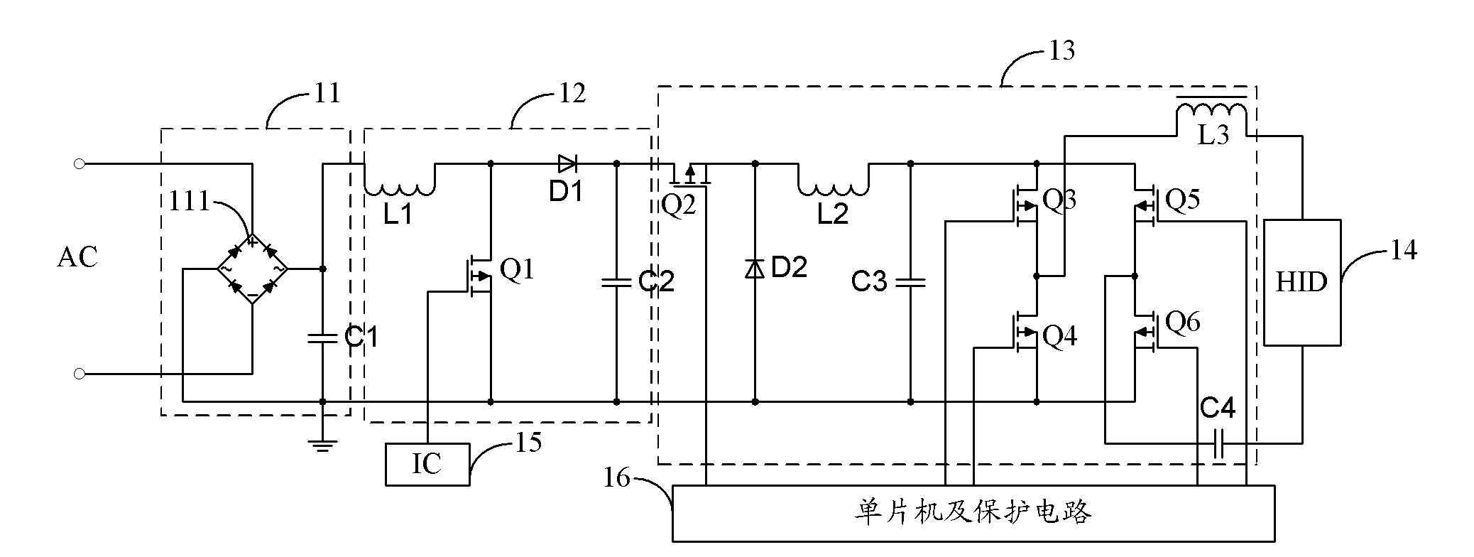
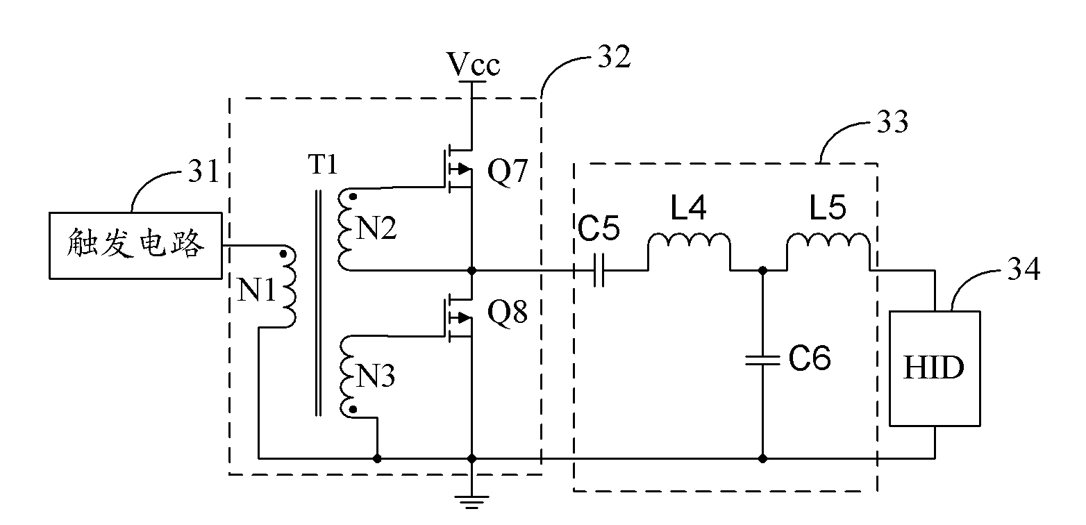
[0029] The embodiment of the present invention utilizes the inherent phase relationship inside the power FET to generate an oscillating signal through the power half-bridge self-excited oscillating circuit, performs impedance matching on the oscillating signal through the filter circuit, and triggers the HID lamp to avoid damage caused by stroboscopic flicker to the human eye. damage and can pass the EMC test.

[0030] figure 2 The structure of the HID electronic ballast circuit provided by an embodiment of the present invention is shown, and for the convenience of description, only the parts rel...


PUM


Abstract

The invention is suitable for the field of electronic technology, and provides a HID (High Intensity Discharge) electronic ballasting circuit, an electronic ballast and an HID lamp. The HID electronic ballasting circuit comprises a trigger circuit, a power half bridge self-excited oscillation circuit and a filtering return circuit, wherein the power half bridge self-excited oscillation circuit utilizes the Miller capacitance Cd of an internal power field effect tube to energize the diagonal capacitance Cgs to realize self-excited oscillation and output a self-excited oscillation signal when the original single pulse output by the trigger circuit is excited; and the filtering return circuit carries out the impedance matching on the self-excited oscillation signal and enables the self-excited oscillation signal converted from a low impedance voltage source to a high impedance constant current source. On the basis of the inherent phase relationship in the power field effect tube, the oscillation signal is generated through the power half bridge self-excited oscillation circuit, and the impedance matching of the oscillation signal is carried out through the filtering return circuit so as to trigger the HID lamp, thereby preventing the human eyes from being damaged by the frequent flashing and passing the electromagnetic compatibility testing.

Description

technical field [0001] The invention belongs to the field of electronic technology, and in particular relates to an HID electronic ballast circuit, an electronic ballast and a high-pressure gas discharge lamp. Background technique [0002] With the increasing demand for environmentally friendly lighting in society, high-pressure gas discharge (High Intensity Discharge, HID) lamps, as a new generation of high-efficiency light sources widely used in the world, have largely replaced halogen lamps and high-pressure mercury lamps with their advantages of energy saving and high brightness. As the most important part of the HID lamp, the ballast determines the quality of the HID lamp. [0003] HID ballasts are divided into HID electronic ballasts and HID inductive ballasts. Among them, HID electronic ballasts have largely replaced HID inductors due to their advantages of constant power, low grid pollution, high power utilization and high electro-optical conversion efficiency. type...

Claims


Application Information

Patent Timeline
Patent Type & Authority Applications(China)
IPC IPC(8): H05B41/288
CPCH05B41/16H05B41/2882
Inventor 谢立山陈裕嘉袁青辉杨红敏
Owner GUANGDONG GREENLIGHT PHOTOELECTRIC TECH
Learn More