Pump arrangement

A pump device, gear pump technology, applied in the direction of pump devices, pumps, fuel injection devices, etc., can solve problems such as wear and clutch wear, and achieve the effect of reducing wear

Inactive Publication Date: 2012-10-24
ROBERT BOSCH GMBH
View PDF6 Cites 0 Cited by
  • Summary
  • Abstract
  • Description
  • Claims
  • Application Information

AI Technical Summary

Problems solved by technology

[0003] A disadvantage of the pump device known from DE 197 36 160 A1 is that abrasive wear occurs in the clutch

Method used


Image

  • Pump arrangement
  • Pump arrangement

Examples


Embodiment Construction

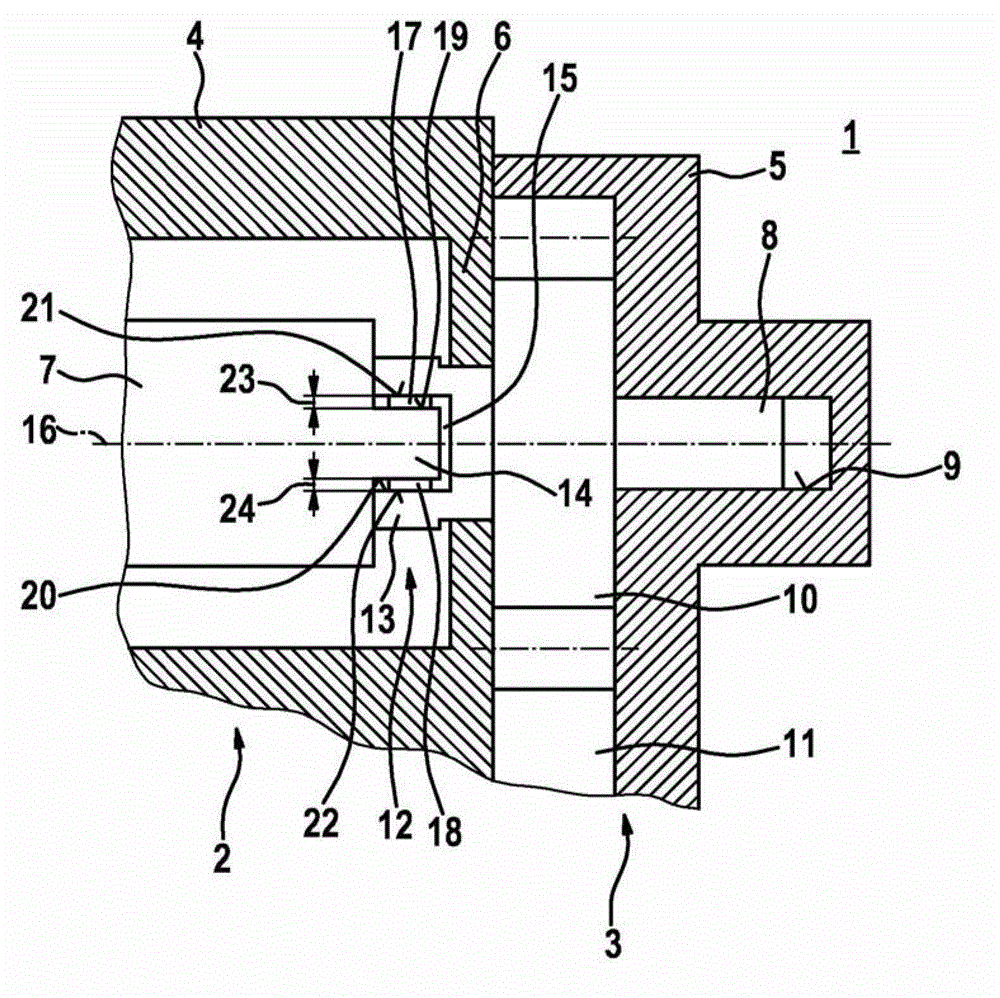
[0014] figure 1 A pump device 1 corresponding to an exemplary embodiment of the invention is shown in a schematic, schematic axial section. The pump device 1 can be used in particular in a fuel injection system of a compressed air self-igniting internal combustion engine. A preferred use of the pump device 1 is in fuel injection systems with fuel distributor strips for storing high-pressure diesel fuel. The pump device 1 is used in this case to deliver fuel to such a fuel distributor bead. However, the pump device 1 according to the invention is also suitable for other applications.

[0015] The pump device 1 has a high-pressure pump 2 and a gear pump 3 . The high-pressure pump 2 has a housing 4 . The gear pump 3 has a housing part 5 designed as a cover 5 , for example. The housing part 5 is connected in a suitable manner to the housing 4 of the high-pressure pump 2 . A separation between the area of ​​the high-pressure pump 2 and the area of ​​the gear pump 3 is hereby ...


PUM


Abstract

The invention relates to a pump arrangement (1), which is used in particular for fuel injection systems of air-compressing, auto-igniting internal combustion engines, comprising a high pressure pump (2), which has a high pressure pump shaft (7), and a gear pump (3), which has a gear pump shaft (8). The invention further relates to a coupling (12) which has at least one sacrificial surface (21, 22) and is provided between the high pressure pump shaft (7) and the gear pump shaft (8).

Description

technical field [0001] The invention relates to a pump device, in particular to a pump device with a high-pressure pump and an external gear pump. The invention specifically relates to the field of a fuel injection device for an air compression, self-ignition internal combustion engine. Background technique [0002] A pump arrangement for high-pressure supply of fuel in an injection system of an internal combustion engine is known from DE 197 36 160 A1. The known pump device has a pump housing for a radial piston pump, a housing part and an end plate for a gear pump. At this time, a cross disc clutch is provided, which drives a shaft connecting the drive shaft of the radial piston pump and the gear pump. [0003] A disadvantage of the pump device known from DE 197 36 160 A1 is that abrasive wear occurs in the clutch. In the conceivable improvement of friction pairs, in particular of the drive shaft material or of the clutch material, in another case, in particular, high l...

Claims


Application Information

Patent Timeline
Patent Type & Authority Applications(China)
IPC IPC(8): F04B23/10F02M39/00F04C2/02
CPCF04C2/10F04C15/0073F04C11/006F02M39/005F04C2210/1044F04B23/103
Inventor A·真特M·格莱纳
Owner ROBERT BOSCH GMBH
Why Eureka
Try Eureka