
Method for driving display device

A technology of a display device and a driving method, applied to static indicators, nonlinear optics, instruments, etc., capable of solving problems such as different brightness

Inactive Publication Date: 2012-10-24
TCL CHINA STAR OPTOELECTRONICS TECH CO LTD
View PDF5 Cites 4 Cited by
  • Summary
  • Abstract
  • Description
  • Claims
  • Application Information

AI Technical Summary

Problems solved by technology

[0006] An object of the present invention is to provide a method for driving a display device to solve the problem in the prior art that different source drive circuits provide data, resulting in different brightness between the upper half region and the lower half region

Method used


Image

  • Method for driving display device
  • Method for driving display device
  • Method for driving display device

Examples


Embodiment Construction

[0022] The following descriptions of the various embodiments refer to the accompanying drawings to illustrate specific embodiments in which the present invention can be practiced.

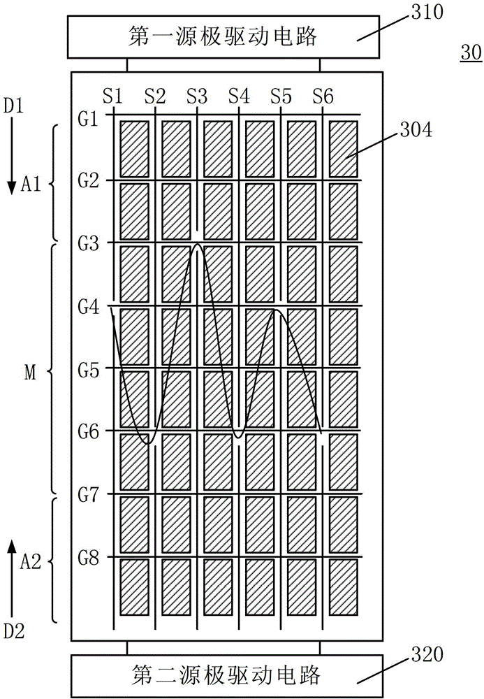
[0023] see image 3 , which is a schematic diagram of a driving method of a display device according to a preferred embodiment of the present invention.

[0024] The display device 30 includes several scanning lines G1-G8, several data lines S1-S6 insulated and intersecting with the scanning lines G1-G8, several pixels 304 defined by the scanning lines G1-G8 and the data lines S1-S6, a first In the source driving circuit 310 and the second source driving circuit 320, each pixel 304 is controlled to be turned on or off by one of the scanning lines G1-G8, and is provided with data by one of the data lines S1-S6.

[0025] The scanning lines G1-G8 are located in a first area A1, a middle area M, and a second area A2 from top to bottom. In this embodiment, the scanning lines G1-G2 are located in the fi...


PUM


Abstract

The invention discloses a method for driving a display device. The display device comprises scanning lines, data lines, pixels, a first source driving circuit and a second source driving circuit, wherein the scanning lines are sequentially positioned in a first region, a middle region and a second region; and each data line is divided into two line segments which are electrically disconnected with each other. The method for driving the display device comprises the following steps of: simultaneously conducting one of the scanning lines in the first region and one of the scanning lines in the second region; supplying data to the pixels electrically connected to the conducted scanning line in the first region from the first source driving circuit through the data lines, and supplying data to the pixels electrically connected to the conducted scanning line in the second region from the second source driving circuit through the data lines; scanning all the scanning lines in the first region and the second region, and then conducting one of the scanning lines in the middle region; and supplying data by the first source driving circuit or the second source driving circuit according to positions of the two electrically disconnected line segments of each data line.

Description

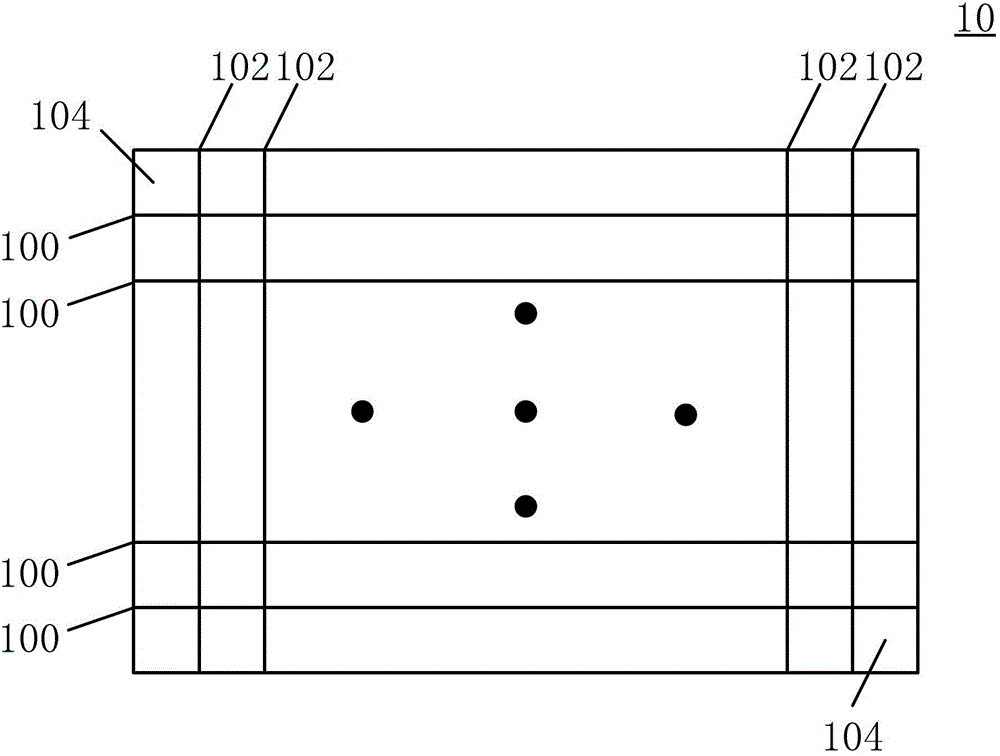
【Technical field】 [0001] The present invention relates to the technical field of display devices, in particular to a driving method of a display device. 【Background technique】 [0002] see figure 1 , which is an existing display device 10, the display device 10 includes several scanning lines 100 (also called gate lines), several data lines 102 (also called source lines) and several pixels 104, each pixel 104 is controlled to be on or off by a corresponding scan line 100 and data is provided by a corresponding data line 102 . [0003] The driving method of the traditional display device 10 is to turn on one scanning line 100 sequentially from top to bottom, and then write data into the pixels 104 controlled by the turned-on scanning line 100 through the data line 102, that is to say, the traditional driving method One scan line 100 is turned on at a time, and the first scan line 100 is driven sequentially after the last scan line 100 is turned on. [0004] In order to spe...

Claims


Application Information

Patent Timeline
Patent Type & Authority Applications(China)
IPC IPC(8): G09G3/20
CPCG02F1/13G09G3/36G09G3/20G09G2300/0426G09G2310/0205G09G2310/0221G09G3/2003G09G2300/0465G09G2320/0233
Inventor 林家强侯鸿龙
Owner TCL CHINA STAR OPTOELECTRONICS TECH CO LTD
Learn More